
Quick Guide


5
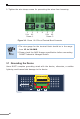
3. Wiring the Power Inputs
The Upper Panel of the Industrial Managed Switch indicates an inlet power
socket and consists of one green terminal block connector with 6 contacts.
Please follow the steps below to insert the power wire.
1.Insert positive/negative DC power wires into Contacts 1 and 2 for Power 1,
or Contacts 5 and 6 for Power 2.
DC9-48V,AC24V
Max. Fault Alarm Loading: 24V, 1A
DI1 DO0 DO1DI0 GNDGND
V1+ V2+
PWR1
PWR2Alarm
DC Input: 9-48V
, 4A max.
AC Input: 24V
, 2A max.
1 2 3 4 5 6
1 2 3 4 5 6
Figure 3-1: IGS-6325-5X1T Upper Panel
Refer to the table below for the Input Voltage and Current values for each
model.
IGS-6325-4T2X IGS-6325-5X1T
DCInputVoltage 9-48VDC 9-48VDC
DC Max. Input Current 3A 4A
ACInputVoltage 24VAC 24VAC
ACMax.InputCurrent 1.5A 2A
PWR1 and PWR2 must provide exactly the same DC voltage for
power load balance while operating with dual power input.