
Quick Guide

5
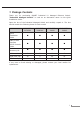
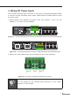
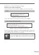
3. Wiring DC Power Inputs
The 6-contact terminal block connector on the panel of Industrial Managed Switch
isused for two DCredundant power inputs. Pleasefollowthe steps below to insert
the power wires.
1.Insert positive and negative DC power wires into contacts 1 and 2 for DC
POWER1,or5and6forDCPOWER2.
DI/DO
FaultR.O.
Ring
AC
DC 2
DC 1
8642
7531
100~240V AC
50/60 Hz
ON
AC POWER
OFF
DC POWER
ON
OFF
DC Input Range:
36V~60V
Fault
GNDGNDDO 1DO 0DI 1DI 0
DC 2DC 1
Figure 3-1: 6-contact terminal block connector of IGS-6325-20T4C4X and IGS-6325-20S4C4X
642
531
Input DC 48-56V
+
FaultDC 1 DC 2
+
Please refer to user’s manual before
connect the DC wire.
CAUTION
GNDGNDDO 1DO 0DI 1DI 0
R.O. DC2
DIDO Fault
Ring DC1
DC POWER
ON
OFF
LNK/ACT
PoE-in-Use
Figure 3-2: 6-contact terminal block connector of IGS-6325-24P4X and IGS-6325-24P4S
2.Tightenthewire-clampscrewsforpreventingthewiresfromloosening.
1 2 3 4 5 6
Power 1 Fault Power 2
+ - + -
Figure 3-3: The pins of 6-contact terminal block connector
Note
The wire gauge for the terminal block should be in the range
between12and24AWG.