Industrial IP67-rated 4-Port 10/100/1000T 802.
Table of Contents 1. Package Contents........................................................................................ 3 2. Hardware Introduction................................................................................. 4 2.1 Physical Dimensions.............................................................................. 4 2.2 Switch Front Panel Layout..................................................................... 5 2.3 LED Indicators....................................................
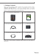
1. Package Contents Thank you for purchasing PLANET Industrial M12 Managed Ethernet Switch. “Industrial Managed Switch” is used as an alternative name in this Quick Installation Guide. Open the box of the Industrial Managed Switch and carefully unpack it. The box should contain the following items: 1 x The Industrial Managed Switch 1 x Quick Installation Guide 1 x 2m 8-pin A-code M12-to-RJ45 UTP Cable 1 x DIN Rail Kit 1 x 1.
2. Hardware Introduction 2.
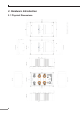
2.2 Switch Front Panel Layout Figure 2-1 shows the front panel of the Industrial Managed Switch. M12 Gigabit Ethernet Port LNK/ACT 1 LNK/ACT 3 M12 Gigabit Ethernet PoE+ Port 2 4 PoE LNK/ACT 5 6 PoE V2 V1 V2 V1 2 M12 Power Input Connector PWR 2 R.O. PWR 1 Ring INPUT DC 48-56V 1 3 FAULT 7 4 6 5 8 Pin Con 1 2 3 4 5 6 7 8 DA+ DA DB+ DC+ DC DB DD+ DD Power, Fault, Ring LEDs PoE IP67 Mgt. IGS-604HPT-M12 Figure 2-2: IGS-604HPT-M12 Front Panel 2.
Per 10/100/1000BASE-T PoE+ Port (Port 3~6) LED LNK/ACT PoE-in-Use Color Function Lights To indicate the port is running in 10/10/1000Mbps speed and successfully established. Blinks To indicate the switch is actively sending or receiving data over that port. Lights To indicate the port is providing 45~55 V DC in-line power. Off To indicate the connected device is not a PoE powered device (PD). Green Orange 2.
M12 A-code Male Connector Pin No. MDI 1000BASE-T Signal ID T568B Color RJ45 connector Pin No.
2.6 M12 DC Power Connector Pin Assignment The front panel of the Industrial Managed Switch provides one M12 A-coded 5-pin male connector for dual DC power input. V2 V1 V2 V1 INPUT DC 48-56V 2.7 M12 DC Power Cable Wiring Please use the power cable with the M12 A-coded 5-pin female connector from the Industrial Managed Switch package for DC power input.
3. Connecting M12 Cable to the IGS-604HPT-M12 Step 1: Turn counterclockwise to remove the waterproof screw nuts of an M12 connector and power input. Step 2: Insert the M12 UTP male connector into the M12 female Gigabit Ethernet port of the Industrial Managed Switch. Step 3: Turn clockwise to tighten the screw nut of the M12 connector and make sure the connection is tight.
Step 4: Insert the M12 power female connector into the M12 male port of the power input. Step 5: Turn clockwise to tighten the screw nut of the M12 power connector. Note Before connecting the DC power cord, please check whether your local DC power source is stable. Make sure to tightly close all interfaces to have waterproof effect.
4. Switch Management 4.1 Requirements Workstations running Windows XP/2003/Vista/7/8/10/2008, MAC OS X or later, Linux, UNIX, or other platforms are compatible with TCP/IP Protocols. Workstations are installed with Ethernet NIC (Network Interface Card) Ethernet Port Connection Network cables -- Use standard network (UTP) cables with RJ45 connectors. The above PC is installed with Web browser and JAVA runtime environment plug-in. Note It is recommended to use Internet Explore 8.
4.3 Logging in the Industrial Managed Switch 1. Use Internet Explorer 8.0 or above Web browser and enter IP address http://192.168.0.100 (default IP address) to access the Web interface. 2. When the following dialog box appears, please enter the default user name and password “admin”. The login screen in Figure 4-1 appears. Default IP Address: 192.168.0.100 Default Username: admin Default Password: admin Figure 4-1: Login Screen 3. After entering the password, the main screen appears as Figure 4-2 shows.
The Switch Menu on the left of the Web page lets you access all the commands and statistics the Industrial Managed Switch provides. Figure 4-3: Switch Menu Note If you are not familiar with Switch functions or the related parameter, press “Help icon” anytime on the Web page to get the help description. Now, you can use the Web management interface to continue the Switch management. Please refer to the user’s manual for more details. 4.
To save all applied changes and set the current configuration as a startup configuration, the startup-configuration file will be loaded automatically across a system reboot. 1. Click System, Save Startup Config. 2. Press the “Save Configuration” button.
5. Recovering Back to Default Configuration IP address has been changed or admin password has been forgotten – 1. Power off the Industrial Managed Switch and remove all the existing connections. 2. Use the straight RJ45 cable to connect to port 1 and port 2 in the loop topology as shown below: 3. Power on the Industrial Managed Switch and 6 LNK/ACT LEDs will be lit. 4. Resetting Industrial Managed Switch to the factory default is done when 6 LNK/ ACT LEDs are lit again. 5.
6. Customer Support Thank you for purchasing PLANET products. You can browse our online FAQ resource and User’s Manual on PLANET Web site first to check if it could solve your issue. If you need more support information, please contact PLANET switch support team. PLANET online FAQ: http://www.planet.com.tw/en/support/faq.php?type=1 Switch support team mail address: support_switch@planet.com.tw IGS-604HPT-M12 User’s Manual: http://www.planet.com.tw/en/support/download.