
User's Manual


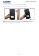
Table Of Contents
- 1. INTRODUCTION
- 2. INSTALLATION
- 3. SWITCH MANAGEMENT
- 4. WEB CONFIGURATION
- 4.1 Main Web page
- 4.2 System
- 4.2.1 System Information
- 4.2.2 IP Configuration
- 4.2.3 IP Status
- 4.2.4 Users Configuration
- 4.2.5 Privilege Levels
- 4.2.6 NTP Configuration
- 4.2.7 Time Configuration
- 4.2.8 UPnP
- 4.2.9 DHCP Relay
- 4.2.10 DHCP Relay Statistics
- 4.2.11 CPU Load
- 4.2.12 System Log
- 4.2.13 Detailed Log
- 4.2.14 Remote Syslog
- 4.2.15 SMTP Configuration
- 4.2.16 Fault Alarm
- 4.2.17 Web Firmware Upgrade
- 4.2.18 TFTP Firmware Upgrade
- 4.2.19 Save Startup Config
- 4.2.20 Configuration Download
- 4.2.21 Configuration Upload
- 4.2.22 Configuration Activate
- 4.2.23 Configuration Delete
- 4.2.24 Image Select
- 4.2.25 Factory Default
- 4.2.26 System Reboot
- 4.3 Simple Network Management Protocol
- 4.4 Port Management
- 4.5 Link Aggregation
- 4.6 VLAN
- 4.7 Spanning Tree Protocol
- 4.8 Multicast
- 4.8.1 IGMP Snooping
- 4.8.2 Profile Table
- 4.8.3 Address Entry
- 4.8.4 IGMP Snooping Configuration
- 4.8.5 IGMP Snooping VLAN Configuration
- 4.8.6 IGMP Snooping Port Group Filtering
- 4.8.7 IGMP Snooping Status
- 4.8.8 IGMP Group Information
- 4.8.9 IGMPv3 Information
- 4.8.10 MLD Snooping Configuration
- 4.8.11 MLD Snooping VLAN Configuration
- 4.8.12 MLD Snooping Port Group Filtering
- 4.8.13 MLD Snooping Status
- 4.8.14 MLD Group Information
- 4.8.15 MLDv2 Information
- 4.8.16 MVR (Multicast VLAN Registration)
- 4.8.17 MVR Status
- 4.8.18 MVR Groups Information
- 4.8.19 MVR SFM Information
- 4.9 Quality of Service
- 4.9.1 Understanding QoS
- 4.9.2 Port Policing
- 4.9.3 Port Classification
- 4.9.4 Port Scheduler
- 4.9.5 Port Shaping
- 4.9.6 Port Tag Remarking
- 4.9.7 Port DSCP
- 4.9.8 DSCP-based QoS
- 4.9.9 DSCP Translation
- 4.9.10 DSCP Classification
- 4.9.11 QoS Control List
- 4.9.12 QCL Status
- 4.9.13 Storm Control Configuration
- 4.9.14 QoS Statistics
- 4.9.15 Voice VLAN Configuration
- 4.9.16 Voice VLAN OUI Table
- 4.10 Access Control List
- 4.11 Authentication
- 4.11.1 Understanding IEEE 802.1X Port-based Authentication
- 4.11.2 Authentication Configuration
- 4.11.3 Network Access Server Configuration
- 4.11.4 Network Access Overview
- 4.11.5 Network Access Statistics
- 4.11.6 RADIUS
- 4.11.7 TACACS+
- 4.11.8 RADIUS Overview
- 4.11.9 RADIUS Details
- 4.11.10 Windows Platform RADIUS Server Configuration
- 4.11.11 802.1X Client Configuration
- 4.12 Security
- 4.12.1 Port Limit Control
- 4.12.2 Access Management
- 4.12.3 Access Management Statistics
- 4.12.4 HTTPs
- 4.12.5 SSH
- 4.12.6 Port Security Status
- 4.12.7 Port Security Detail
- 4.12.8 DHCP Snooping
- 4.12.9 Snooping Table
- 4.12.10 IP Source Guard Configuration
- 4.12.11 IP Source Guard Static Table
- 4.12.12 Dynamic IP Source Guard Table
- 4.12.13 ARP Inspection
- 4.12.14 ARP Inspection Static Table
- 4.12.15 Dynamic ARP Inspection Table
- 4.13 MAC Address Table
- 4.14 LLDP
- 4.15 Network Diagnostics
- 4.16 Loop Protection
- 4.17 RMON
- 4.18 PTP
- 4.19 Ring
- 5. SWITCH OPERATION
- 6. TROUBLESHOOTING
- APPENDIX A: Networking Connection
- APPENDIX B: GLOSSARY

User’s Manual of IGS-5227-Series
37
2.3 Installing the Industrial Managed Switch
This section describes how to install your Industrial Managed Switch and make connections to the Industrial Managed Switch.
Please read the following topics and perform the procedures in the order being presented. To install your Industrial Managed
Switch on a desktop or shelf, simply complete the following steps.
In this paragraph, we will describe how to install the Industrial Managed Switch and the installation points attended to it.
2.3.1 Installation Steps
1. Unpack the Industrial Managed Switch
2. Check if the DIN-rail is screwed on the Industrial Managed Switch or not. If the DIN-rail is not screwed on the
Industrial Managed Switch, please refer to DIN-rail Mounting section for DIN-rail installation. If users want to
wall-mount the Industrial Managed Switch, please refer to the Wall-mount Plate Mounting section for wall-mount plate
installation.
3. To hang the Industrial Managed Switch on the DIN-rail track or wall.
4. Power on the Industrial Managed Switch. Please refer to the Wiring the Power Inputs section for the information
about how to wire the power. The power LED on the Industrial Managed Switch will light up. Please refer to the LED
Indicators section for indication of LED lights.
5. Prepare the twisted-pair, straight-through Category 5 cable for Ethernet connection.
6. Insert one side of RJ45 cable (category 5) into the Industrial Managed Switch Ethernet port (RJ45 port) while the
other side to the network device’s Ethernet port (RJ45 port), e.g., Switch PC or Server. The UTP port (RJ45) LED on the
Industrial Managed Switch will light up when the cable is connected with the network device. Please refer to the LED
Indicators section for LED indication.
Make sure that the connected network devices support MDI/MDI-X. If it does not support,
use the crossover Category 5 cable.
7. When all connections are set and all LED lights show normal, the installation is completed.
2.3.2 DIN-rail Mounting
This section describes how to install the Industrial Managed Switch. There are two methods to install the Industrial
Managed Switch -- DIN-rail mounting and wall-mount plate mounting. Please read the following topics and perform the
procedures in the order being presented.