
User's Manual
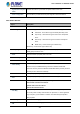


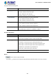


Table Of Contents
- 1. INTRODUCTION
- 2. INSTALLATION
- 3. SWITCH MANAGEMENT
- 4. WEB CONFIGURATION
- 4.1 Main Web page
- 4.2 System
- 4.2.1 System Information
- 4.2.2 IP Configuration
- 4.2.3 IP Status
- 4.2.4 Users Configuration
- 4.2.5 Privilege Levels
- 4.2.6 NTP Configuration
- 4.2.7 Time Configuration
- 4.2.8 UPnP
- 4.2.9 DHCP Relay
- 4.2.10 DHCP Relay Statistics
- 4.2.11 CPU Load
- 4.2.12 System Log
- 4.2.13 Detailed Log
- 4.2.14 Remote Syslog
- 4.2.15 SMTP Configuration
- 4.2.16 Fault Alarm
- 4.2.17 Web Firmware Upgrade
- 4.2.18 TFTP Firmware Upgrade
- 4.2.19 Save Startup Config
- 4.2.20 Configuration Download
- 4.2.21 Configuration Upload
- 4.2.22 Configuration Activate
- 4.2.23 Configuration Delete
- 4.2.24 Image Select
- 4.2.25 Factory Default
- 4.2.26 System Reboot
- 4.3 Simple Network Management Protocol
- 4.4 Port Management
- 4.5 Link Aggregation
- 4.6 VLAN
- 4.7 Spanning Tree Protocol
- 4.8 Multicast
- 4.8.1 IGMP Snooping
- 4.8.2 Profile Table
- 4.8.3 Address Entry
- 4.8.4 IGMP Snooping Configuration
- 4.8.5 IGMP Snooping VLAN Configuration
- 4.8.6 IGMP Snooping Port Group Filtering
- 4.8.7 IGMP Snooping Status
- 4.8.8 IGMP Group Information
- 4.8.9 IGMPv3 Information
- 4.8.10 MLD Snooping Configuration
- 4.8.11 MLD Snooping VLAN Configuration
- 4.8.12 MLD Snooping Port Group Filtering
- 4.8.13 MLD Snooping Status
- 4.8.14 MLD Group Information
- 4.8.15 MLDv2 Information
- 4.8.16 MVR (Multicast VLAN Registration)
- 4.8.17 MVR Status
- 4.8.18 MVR Groups Information
- 4.8.19 MVR SFM Information
- 4.9 Quality of Service
- 4.9.1 Understanding QoS
- 4.9.2 Port Policing
- 4.9.3 Port Classification
- 4.9.4 Port Scheduler
- 4.9.5 Port Shaping
- 4.9.6 Port Tag Remarking
- 4.9.7 Port DSCP
- 4.9.8 DSCP-based QoS
- 4.9.9 DSCP Translation
- 4.9.10 DSCP Classification
- 4.9.11 QoS Control List
- 4.9.12 QCL Status
- 4.9.13 Storm Control Configuration
- 4.9.14 QoS Statistics
- 4.9.15 Voice VLAN Configuration
- 4.9.16 Voice VLAN OUI Table
- 4.10 Access Control List
- 4.11 Authentication
- 4.11.1 Understanding IEEE 802.1X Port-based Authentication
- 4.11.2 Authentication Configuration
- 4.11.3 Network Access Server Configuration
- 4.11.4 Network Access Overview
- 4.11.5 Network Access Statistics
- 4.11.6 RADIUS
- 4.11.7 TACACS+
- 4.11.8 RADIUS Overview
- 4.11.9 RADIUS Details
- 4.11.10 Windows Platform RADIUS Server Configuration
- 4.11.11 802.1X Client Configuration
- 4.12 Security
- 4.12.1 Port Limit Control
- 4.12.2 Access Management
- 4.12.3 Access Management Statistics
- 4.12.4 HTTPs
- 4.12.5 SSH
- 4.12.6 Port Security Status
- 4.12.7 Port Security Detail
- 4.12.8 DHCP Snooping
- 4.12.9 Snooping Table
- 4.12.10 IP Source Guard Configuration
- 4.12.11 IP Source Guard Static Table
- 4.12.12 Dynamic IP Source Guard Table
- 4.12.13 ARP Inspection
- 4.12.14 ARP Inspection Static Table
- 4.12.15 Dynamic ARP Inspection Table
- 4.13 MAC Address Table
- 4.14 LLDP
- 4.15 Network Diagnostics
- 4.16 Loop Protection
- 4.17 RMON
- 4.18 PTP
- 4.19 Ring
- 5. SWITCH OPERATION
- 6. TROUBLESHOOTING
- APPENDIX A: Networking Connection
- APPENDIX B: GLOSSARY

User’s Manual of IGS-5227-Series
339
• Peer MEP ID
This value will become an expected MEP ID in a received CCM - see 'cMEP'.
• Unicast Peer MAC
This MAC will be used when unicast is selected with this peer MEP. Also this
MAC is used to create HW checking of receiving CCM PDU (LOC detection) from
t h i s M E P.
• cLOC
Fault Cause indicating that no CCM has been received (in 3,5 periods) - from this
peer MEP.
• cRDI
Fault Cause indicating that a CCM is received with Remote Defect Indication -
from this peer MEP.
• cPeriod
Fault Cause indicating that a CCM is received with a period different what is
configured for this MEP - from this peer MEP.
• cPriority
Fault Cause indicating that a CCM is received with a priority different what is
configured for this MEP - from this peer MEP.
Buttons
: Click to add a new peer MEP.
Functional Configuration
Continuity Check:
Object Description
• Enable
Continuity Check based on transmitting/receiving CCM PDU can be
enabled/disabled. The CCM PDU is always transmitted as Multi-cast Class 1.
• Priority
The priority to be inserted as PCP bits in TAG (if any). To enable both Continuity
Check and Loss Measurement implemented on SW-based CCM, 'Priority' has to
be the same.
• Frame rate
Selecting the frame rate of CCM PDU. This is the inverse of transmission period
as described in Y.1731. This value has the following uses:
* The transmission rate of the CCM PDU.
* Fault Cause cLOC is declared if no CCM PDU has been received within 3.5
periods - see 'cLOC'.
* Fault Cause cPeriod is declared if a CCM PDU has been received with different
period - see 'cPeriod'.
Selecting 300f/sec or 100f/sec will configure HW-based CCM (if possible).
Selecting other frame rates will configure SW-based CCM. To enable both
Continuity Check and Loss Measurement implemented on SW-based CCM,
'Frame Rate' has to be the same.