
User's Manual


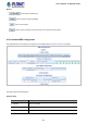


Table Of Contents
- 1. INTRODUCTION
- 2. INSTALLATION
- 3. SWITCH MANAGEMENT
- 4. WEB CONFIGURATION
- 4.1 Main Web page
- 4.2 System
- 4.2.1 System Information
- 4.2.2 IP Configuration
- 4.2.3 IP Status
- 4.2.4 Users Configuration
- 4.2.5 Privilege Levels
- 4.2.6 NTP Configuration
- 4.2.7 Time Configuration
- 4.2.8 UPnP
- 4.2.9 DHCP Relay
- 4.2.10 DHCP Relay Statistics
- 4.2.11 CPU Load
- 4.2.12 System Log
- 4.2.13 Detailed Log
- 4.2.14 Remote Syslog
- 4.2.15 SMTP Configuration
- 4.2.16 Fault Alarm
- 4.2.17 Web Firmware Upgrade
- 4.2.18 TFTP Firmware Upgrade
- 4.2.19 Save Startup Config
- 4.2.20 Configuration Download
- 4.2.21 Configuration Upload
- 4.2.22 Configuration Activate
- 4.2.23 Configuration Delete
- 4.2.24 Image Select
- 4.2.25 Factory Default
- 4.2.26 System Reboot
- 4.3 Simple Network Management Protocol
- 4.4 Port Management
- 4.5 Link Aggregation
- 4.6 VLAN
- 4.7 Spanning Tree Protocol
- 4.8 Multicast
- 4.8.1 IGMP Snooping
- 4.8.2 Profile Table
- 4.8.3 Address Entry
- 4.8.4 IGMP Snooping Configuration
- 4.8.5 IGMP Snooping VLAN Configuration
- 4.8.6 IGMP Snooping Port Group Filtering
- 4.8.7 IGMP Snooping Status
- 4.8.8 IGMP Group Information
- 4.8.9 IGMPv3 Information
- 4.8.10 MLD Snooping Configuration
- 4.8.11 MLD Snooping VLAN Configuration
- 4.8.12 MLD Snooping Port Group Filtering
- 4.8.13 MLD Snooping Status
- 4.8.14 MLD Group Information
- 4.8.15 MLDv2 Information
- 4.8.16 MVR (Multicast VLAN Registration)
- 4.8.17 MVR Status
- 4.8.18 MVR Groups Information
- 4.8.19 MVR SFM Information
- 4.9 Quality of Service
- 4.9.1 Understanding QoS
- 4.9.2 Port Policing
- 4.9.3 Port Classification
- 4.9.4 Port Scheduler
- 4.9.5 Port Shaping
- 4.9.6 Port Tag Remarking
- 4.9.7 Port DSCP
- 4.9.8 DSCP-based QoS
- 4.9.9 DSCP Translation
- 4.9.10 DSCP Classification
- 4.9.11 QoS Control List
- 4.9.12 QCL Status
- 4.9.13 Storm Control Configuration
- 4.9.14 QoS Statistics
- 4.9.15 Voice VLAN Configuration
- 4.9.16 Voice VLAN OUI Table
- 4.10 Access Control List
- 4.11 Authentication
- 4.11.1 Understanding IEEE 802.1X Port-based Authentication
- 4.11.2 Authentication Configuration
- 4.11.3 Network Access Server Configuration
- 4.11.4 Network Access Overview
- 4.11.5 Network Access Statistics
- 4.11.6 RADIUS
- 4.11.7 TACACS+
- 4.11.8 RADIUS Overview
- 4.11.9 RADIUS Details
- 4.11.10 Windows Platform RADIUS Server Configuration
- 4.11.11 802.1X Client Configuration
- 4.12 Security
- 4.12.1 Port Limit Control
- 4.12.2 Access Management
- 4.12.3 Access Management Statistics
- 4.12.4 HTTPs
- 4.12.5 SSH
- 4.12.6 Port Security Status
- 4.12.7 Port Security Detail
- 4.12.8 DHCP Snooping
- 4.12.9 Snooping Table
- 4.12.10 IP Source Guard Configuration
- 4.12.11 IP Source Guard Static Table
- 4.12.12 Dynamic IP Source Guard Table
- 4.12.13 ARP Inspection
- 4.12.14 ARP Inspection Static Table
- 4.12.15 Dynamic ARP Inspection Table
- 4.13 MAC Address Table
- 4.14 LLDP
- 4.15 Network Diagnostics
- 4.16 Loop Protection
- 4.17 RMON
- 4.18 PTP
- 4.19 Ring
- 5. SWITCH OPERATION
- 6. TROUBLESHOOTING
- APPENDIX A: Networking Connection
- APPENDIX B: GLOSSARY

User’s Manual of IGS-5227-Series
335
4.19 Ring
ITU-T G.8032 Ethernet Ring protection switching (ERPS) is a link layer protocol applied on Ethernet loop protection to
provide sub-50ms protection and recovery switching for Ethernet traffic in a ring topology.
ERPS provides a faster redundant recovery than Spanning Tree topology. The action is similar to STP or RSTP, but the
algorithms between them are not the same. In the Ring topology, every switch should be enabled with Ring function and two
ports should be assigned as the member ports in the ERPS. Only one switch in the Ring group would be set as the RPL owner
switch that one port would be blocked, called owner port, and PRL neighbour switch has one port that one port would be
blocked, called neighbour port that connect to owner port directly and this link is called the Ring Protection Link or RPL.
Each switch will sends ETH-CCM message to check the link status in the ring group. When the failure of network connection
occurs, the nodes block the failed link and report the signal failure message, the RPL owner switch will automatically unblocks
the PRL to recover from the failure.