
User's Manual


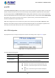

Table Of Contents
- 1. INTRODUCTION
- 2. INSTALLATION
- 3. SWITCH MANAGEMENT
- 4. WEB CONFIGURATION
- 4.1 Main Web page
- 4.2 System
- 4.2.1 System Information
- 4.2.2 IP Configuration
- 4.2.3 IP Status
- 4.2.4 Users Configuration
- 4.2.5 Privilege Levels
- 4.2.6 NTP Configuration
- 4.2.7 Time Configuration
- 4.2.8 UPnP
- 4.2.9 DHCP Relay
- 4.2.10 DHCP Relay Statistics
- 4.2.11 CPU Load
- 4.2.12 System Log
- 4.2.13 Detailed Log
- 4.2.14 Remote Syslog
- 4.2.15 SMTP Configuration
- 4.2.16 Fault Alarm
- 4.2.17 Web Firmware Upgrade
- 4.2.18 TFTP Firmware Upgrade
- 4.2.19 Save Startup Config
- 4.2.20 Configuration Download
- 4.2.21 Configuration Upload
- 4.2.22 Configuration Activate
- 4.2.23 Configuration Delete
- 4.2.24 Image Select
- 4.2.25 Factory Default
- 4.2.26 System Reboot
- 4.3 Simple Network Management Protocol
- 4.4 Port Management
- 4.5 Link Aggregation
- 4.6 VLAN
- 4.7 Spanning Tree Protocol
- 4.8 Multicast
- 4.8.1 IGMP Snooping
- 4.8.2 Profile Table
- 4.8.3 Address Entry
- 4.8.4 IGMP Snooping Configuration
- 4.8.5 IGMP Snooping VLAN Configuration
- 4.8.6 IGMP Snooping Port Group Filtering
- 4.8.7 IGMP Snooping Status
- 4.8.8 IGMP Group Information
- 4.8.9 IGMPv3 Information
- 4.8.10 MLD Snooping Configuration
- 4.8.11 MLD Snooping VLAN Configuration
- 4.8.12 MLD Snooping Port Group Filtering
- 4.8.13 MLD Snooping Status
- 4.8.14 MLD Group Information
- 4.8.15 MLDv2 Information
- 4.8.16 MVR (Multicast VLAN Registration)
- 4.8.17 MVR Status
- 4.8.18 MVR Groups Information
- 4.8.19 MVR SFM Information
- 4.9 Quality of Service
- 4.9.1 Understanding QoS
- 4.9.2 Port Policing
- 4.9.3 Port Classification
- 4.9.4 Port Scheduler
- 4.9.5 Port Shaping
- 4.9.6 Port Tag Remarking
- 4.9.7 Port DSCP
- 4.9.8 DSCP-based QoS
- 4.9.9 DSCP Translation
- 4.9.10 DSCP Classification
- 4.9.11 QoS Control List
- 4.9.12 QCL Status
- 4.9.13 Storm Control Configuration
- 4.9.14 QoS Statistics
- 4.9.15 Voice VLAN Configuration
- 4.9.16 Voice VLAN OUI Table
- 4.10 Access Control List
- 4.11 Authentication
- 4.11.1 Understanding IEEE 802.1X Port-based Authentication
- 4.11.2 Authentication Configuration
- 4.11.3 Network Access Server Configuration
- 4.11.4 Network Access Overview
- 4.11.5 Network Access Statistics
- 4.11.6 RADIUS
- 4.11.7 TACACS+
- 4.11.8 RADIUS Overview
- 4.11.9 RADIUS Details
- 4.11.10 Windows Platform RADIUS Server Configuration
- 4.11.11 802.1X Client Configuration
- 4.12 Security
- 4.12.1 Port Limit Control
- 4.12.2 Access Management
- 4.12.3 Access Management Statistics
- 4.12.4 HTTPs
- 4.12.5 SSH
- 4.12.6 Port Security Status
- 4.12.7 Port Security Detail
- 4.12.8 DHCP Snooping
- 4.12.9 Snooping Table
- 4.12.10 IP Source Guard Configuration
- 4.12.11 IP Source Guard Static Table
- 4.12.12 Dynamic IP Source Guard Table
- 4.12.13 ARP Inspection
- 4.12.14 ARP Inspection Static Table
- 4.12.15 Dynamic ARP Inspection Table
- 4.13 MAC Address Table
- 4.14 LLDP
- 4.15 Network Diagnostics
- 4.16 Loop Protection
- 4.17 RMON
- 4.18 PTP
- 4.19 Ring
- 5. SWITCH OPERATION
- 6. TROUBLESHOOTING
- APPENDIX A: Networking Connection
- APPENDIX B: GLOSSARY

User’s Manual of IGS-5227-Series
329
4.18 PTP
The Precision Time Protocol (PTP) is a protocol used to synchronize clocks throughout a computer network. On a local area
network, it achieves clock accuracy in the sub-microsecond range, making it suitable for measurement and control systems.
PTP was originally defined in the IEEE 1588-2002 standard, officially entitled "Standard for a Precision Clock Synchronization
Protocol for Networked Measurement and Control Systems" and published in 2002. In 2008 a revised standard, IEEE 588-2008
was released. This new version, also known as PTP Version 2, improves accuracy, precision and robustness but is not
backwards compatible with the original 2002 version.
"IEEE 1588 is designed to fill a niche not well served by either of the two dominant protocols, NTP and GPS. IEEE 1588 is
designed for local systems requiring accuracies beyond those attainable using NTP. It is also designed for applications that
cannot bear the cost of a GPS receiver at each node, or for which GPS signals are inaccessible."
4.18.1 PTP Configuration
This page allows the user to configure and inspect the current PTP clock settings. screen in Figure 4-18-1 appears.
Figure 4-18-1: PTP Configuration Screenshot
The page includes the following fields:
Object Description
• Delete
Check this box and click on 'Save' to delete the clock instance.
• Clock Instance
Indicates the Instance of a particular Clock Instance [0..3].
Click on the Clock Instance number to edit the Clock details
• Device Type
Indicates the Type of the Clock Instance. There are five Device Types.
Ord-Bound - clock's Device Type is Ordinary-Boundary Clock.
P2p Transp - clock's Device Type is Peer to Peer Transparent
Clock.
E2e Transp - clock's Device Type is End to End Transparent
Clock.