
User's Manual

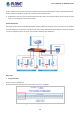


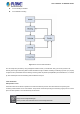
Table Of Contents
- 1. INTRODUCTION
- 2. INSTALLATION
- 3. SWITCH MANAGEMENT
- 4. WEB CONFIGURATION
- 4.1 Main Web page
- 4.2 System
- 4.2.1 System Information
- 4.2.2 IP Configuration
- 4.2.3 IP Status
- 4.2.4 Users Configuration
- 4.2.5 Privilege Levels
- 4.2.6 NTP Configuration
- 4.2.7 Time Configuration
- 4.2.8 UPnP
- 4.2.9 DHCP Relay
- 4.2.10 DHCP Relay Statistics
- 4.2.11 CPU Load
- 4.2.12 System Log
- 4.2.13 Detailed Log
- 4.2.14 Remote Syslog
- 4.2.15 SMTP Configuration
- 4.2.16 Fault Alarm
- 4.2.17 Web Firmware Upgrade
- 4.2.18 TFTP Firmware Upgrade
- 4.2.19 Save Startup Config
- 4.2.20 Configuration Download
- 4.2.21 Configuration Upload
- 4.2.22 Configuration Activate
- 4.2.23 Configuration Delete
- 4.2.24 Image Select
- 4.2.25 Factory Default
- 4.2.26 System Reboot
- 4.3 Simple Network Management Protocol
- 4.4 Port Management
- 4.5 Link Aggregation
- 4.6 VLAN
- 4.7 Spanning Tree Protocol
- 4.8 Multicast
- 4.8.1 IGMP Snooping
- 4.8.2 Profile Table
- 4.8.3 Address Entry
- 4.8.4 IGMP Snooping Configuration
- 4.8.5 IGMP Snooping VLAN Configuration
- 4.8.6 IGMP Snooping Port Group Filtering
- 4.8.7 IGMP Snooping Status
- 4.8.8 IGMP Group Information
- 4.8.9 IGMPv3 Information
- 4.8.10 MLD Snooping Configuration
- 4.8.11 MLD Snooping VLAN Configuration
- 4.8.12 MLD Snooping Port Group Filtering
- 4.8.13 MLD Snooping Status
- 4.8.14 MLD Group Information
- 4.8.15 MLDv2 Information
- 4.8.16 MVR (Multicast VLAN Registration)
- 4.8.17 MVR Status
- 4.8.18 MVR Groups Information
- 4.8.19 MVR SFM Information
- 4.9 Quality of Service
- 4.9.1 Understanding QoS
- 4.9.2 Port Policing
- 4.9.3 Port Classification
- 4.9.4 Port Scheduler
- 4.9.5 Port Shaping
- 4.9.6 Port Tag Remarking
- 4.9.7 Port DSCP
- 4.9.8 DSCP-based QoS
- 4.9.9 DSCP Translation
- 4.9.10 DSCP Classification
- 4.9.11 QoS Control List
- 4.9.12 QCL Status
- 4.9.13 Storm Control Configuration
- 4.9.14 QoS Statistics
- 4.9.15 Voice VLAN Configuration
- 4.9.16 Voice VLAN OUI Table
- 4.10 Access Control List
- 4.11 Authentication
- 4.11.1 Understanding IEEE 802.1X Port-based Authentication
- 4.11.2 Authentication Configuration
- 4.11.3 Network Access Server Configuration
- 4.11.4 Network Access Overview
- 4.11.5 Network Access Statistics
- 4.11.6 RADIUS
- 4.11.7 TACACS+
- 4.11.8 RADIUS Overview
- 4.11.9 RADIUS Details
- 4.11.10 Windows Platform RADIUS Server Configuration
- 4.11.11 802.1X Client Configuration
- 4.12 Security
- 4.12.1 Port Limit Control
- 4.12.2 Access Management
- 4.12.3 Access Management Statistics
- 4.12.4 HTTPs
- 4.12.5 SSH
- 4.12.6 Port Security Status
- 4.12.7 Port Security Detail
- 4.12.8 DHCP Snooping
- 4.12.9 Snooping Table
- 4.12.10 IP Source Guard Configuration
- 4.12.11 IP Source Guard Static Table
- 4.12.12 Dynamic IP Source Guard Table
- 4.12.13 ARP Inspection
- 4.12.14 ARP Inspection Static Table
- 4.12.15 Dynamic ARP Inspection Table
- 4.13 MAC Address Table
- 4.14 LLDP
- 4.15 Network Diagnostics
- 4.16 Loop Protection
- 4.17 RMON
- 4.18 PTP
- 4.19 Ring
- 5. SWITCH OPERATION
- 6. TROUBLESHOOTING
- APPENDIX A: Networking Connection
- APPENDIX B: GLOSSARY

User’s Manual of IGS-5227-Series
132
VLAN 2 members of Port-1 to Port-3 and VLAN 3 members of Port-4 to Port-6 also belong to VLAN 1. But with different PVID
settings, packets from VLAN 2 or VLAN 3 are not able to access to the other VLAN.
6. Repeat Steps 1 to 6 to set up the VLAN Trunk port at the partner switch. To add more VLANs to join the VLAN trunk, repeat
Steps 1 to 3 to assign the Trunk port to the VLANs.
4.6.8.3 Port Isolate
The diagram shows how the Industrial Managed Switch handles isolated and promiscuous ports, and the each PC is not able to
access the isolated port of each other’s PCs. But they all need to access with the same server/AP/Printer. This section will show
you how to configure the port for the server – that could be accessed by each isolated port.
Setup steps
1. Assign Port Mode
Set Port-1~Port-4 in Isolated port.
Set Port-5 and Port-6 in Promiscuous port. The screen in Figure 4-6-16 appears.
Figure 4-6-17: The Configuration of Isolated and Promiscuous Port