Industrial IP67-rated 6-Port Gigabit Managed Ethernet Switch (-40~75 degrees C) IGS-5227-6T/IGS-5227-6MT/IGS-5227-6MT-X Quick Installation Guide
Table of Contents 1. Package Contents........................................................................................ 3 2. Making Waterproof RJ45 Cable (IGS-5227-6T)............................................... 4 3. Connecting Waterproof Cable to the IGS-5227-6T.......................................... 7 4. M12 A-coded Connector Pin Assignment.......................................................10 5. M12 (8-pin, A-coded Male) to RJ45 (8-pin) Straight-through UTP Cabling........11 6.
1. Package Contents Thank you for purchasing PLANET Industrial L2+ Managed Ethernet Switch. “Industrial Managed Switch” is used as an alternative name in this Quick Installation Guide. Open the box of the Industrial Managed Switch and carefully unpack it. The box should contain the following items: zz The Industrial Managed Switch (IGS-5227-6T/IGS-5227-6MT/IGS-5227-6MT-X) x 1 zz Quick Installation Guide x 1 zz 1.
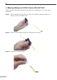
2. Making Waterproof RJ45 Cable (IGS-5227-6T) Please read the following instructions and follow the procedures in the order being presented: Step 1: Take a waterproof RJ45 jack out from the Industrial Managed Switch box and get hold of one RJ45 cable. Step 2: Insert the RJ45 cable through the waterproof RJ45 jack. Step 3: Prepare an RJ45 connector.
Step 4: Put the RJ45 connector in place with cable crimper. The standard RJ45 receptacle/connector There are 8 wires on a standard UTP/STP cable and each wire is color-coded.
Step 5: To lock in the RJ45 connector, pull back the cable till the connector nicely fits into the waterproof connector hole. 1. Use only the waterproof RJ45 connector provided in the package of the IGS-5227-6T. 2.If the waterproof RJ45 connector is found missing or damaged, please contact your local reseller where you purchased from. If the new waterproof RJ45 connector is obtained from PLANET, make sure its dimensions are the same. Note 3.
3. Connecting Waterproof Cable to the IGS-5227-6T Note Follow all the connecting waterproof cable steps as shown in the example. Step 1: Turn counterclockwise to remove the waterproof screw nuts of a RJ45 port and power input. Step 2: Insert the waterproof RJ45 connector into the port of the Industrial Managed Switch.
Step 3: Turn clockwise to tighten the screw nut of the waterproof RJ45 connector. Step 4: Insert the waterproof M12 power connector into the port of the power input.
Step 5: Turn clockwise to tighten the screw nut of the waterproof M12 power connector. 1. Make sure to tightly close all interfaces to have waterproof effect. 2. Before connecting the DC power cord, please check whether your Note local DC power source is stable.
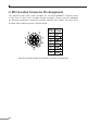
4. M12 A-coded Connector Pin Assignment The IGS-5227-6MT front panel provides six 10/100/1000BASE-T Ethernet ports in the form of M12 8-pin A-coded female connector. These ports are designed for Ethernet equipment connection through Cat5/5e UTP cables.
5. M12 (8-pin, A-coded Male) to RJ45 (8-pin) Straightthrough UTP Cabling M12 A-code Male Connector Pin No. MDI 1000BASE-T Signal ID T568B Color RJ45 Connector Pin No.
6. M12 X-coded Connector Pin Assignment The IGS-5227-6MT-X front panel provides six 10/100/1000BASE-T Ethernet ports in the form of M12 8-pin X-coded female connector. These ports are designed for Ethernet equipment connection through Cat5/5e UTP cables.
7. M12 (8-pin, X-coded Male) to RJ45 (8-pin) Straightthrough UTP Cabling M12 X-code Male Connector Pin No. MDI 1000BASE-T Signal ID T568B Color RJ45 Connector Pin No.
8. Connecting M12 Cable to the IGS-5227-6MT/ IGS-5227-6MT-X Note Follow all the connecting M12 cable to the IGS-5227-6MT/IGS5227-6MT-X steps as shown in the example. Step 1: Turn counterclockwise to remove the waterproof screw nuts of an M12 connector and power input. Step 2: Insert the M12 UTP male connector into the M12 female Gigabit Ethernet port of the Industrial Managed Switch. Step 3: Turn clockwise to tighten the screw nut of the M12 connector and make sure the connection is tight.
Step 4: Insert the M12 power female connector into the M12 male port of the power input. Step 5: Turn clockwise to tighten the screw nut of the M12 power connector. Note Note Before connecting the DC power cord, please check whether your local DC power source is stable. Make sure to tightly close all interfaces to have waterproof effect.
9. M12 DC Power Cable Pin Assignment The front panel of the Industrial Managed Switch provides one M12 DC power 5-pin male connector for DC power input. Please use the power cable with the M12 DC power 5-pin female connector from the Industrial Managed Switch package for DC power input.
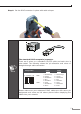
10. Requirements Workstations running Windows XP/2003/Vista/7/8/10/2008, MAC OS X or later, Linux, UNIX, or other platforms are compatible with TCP/IP Protocols. Workstations are installed with Ethernet NIC (Network Interface Card) Ethernet Port Connection zz Network cables -- Use standard network (UTP) cables with RJ45 connectors. zz The above PC is installed with Web browser and JAVA runtime environment plugin. Note It is recommended to use Internet Explore 8.
11. Starting Web Management The following shows how to start up the Web Management of the Industrial Managed Switch. Note the Industrial Managed Switch is configured through an Ethernet connection. Please make sure the manager PC must be set on the same IP subnet address. For example, the default IP address of the Industrial Managed Switch is 192.168.0.100, then the manager PC should be set at 192.168.0.x (where x is a number between 1 and 254, except 100), and the default subnet mask is 255.255.255.0.
Logging in to the Industrial Managed Switch 1. Use Internet Explorer 8.0 or above Web browser and enter IP address http://192.168.0.100 (default IP address) to access the Web interface. 2. When the following dialog box appears, please enter the default user name and password “admin”. The login screen in Figure 11-2 appears. Default Username: admin Default Password: admin Figure 11-2: Login Screen 3. After entering the password, the main screen appears as Figure 11-3 shows.
The Switch Menu on the left of the Web page lets you access all the commands and statistics the Industrial Managed Switch provides. Figure 11-4: Switch Menu Note If you are not familiar with Switch functions or the related parameter, press “Help icon” anytime on the Web page to get the help description. Now, you can use the Web management interface to continue the Switch management. Please refer to the user’s manual for more details.
12. Saving Configuration via Web In the Industrial Managed Switch, the running configuration file is stored in the RAM. In the current version, the running configuration sequence of runningconfig can be saved from the RAM to FLASH by executing save startup config command, so that the running configuration sequence becomes the startup configuration file, which is called configuration save.
13. Recovering Back to Default Configuration IP address has been changed or admin password has been forgotten – Note Follow all the recovering back to default configuration steps as shown in the example. 1. Power off the Industrial Managed Switch and remove all the existing connections. 2. Use the straight RJ45 cable to connect to port 1 and port 2 in the loop topology as shown below: 3. Power on the Industrial Managed Switch and 6 LNK/ACT LEDs will be lit. 4.
14. Customer Support Thank you for purchasing PLANET products. You can browse our online FAQ resource and User’s Manual on PLANET Web site first to check if it could solve your issue. If you need more support information, please contact PLANET switch support team. PLANET online FAQ: http://www.planet.com.tw/en/support/faq.php?type=1 Switch support team mail address: support_switch@planet.com.tw IGS-5227-6T/IGS-5227-6MT/IGS-5227-6MT-X User’s Manual: http://www.planet.com.tw/en/support/download.