
Quick Guide

5
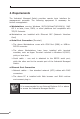
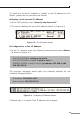
3. Wiring the Power Inputs
The Upper Panel of the Industrial Managed Switch indicates a DC
inlet power socket and consists of one terminal block connector within
6 contacts. Please follow the steps below to insert the power wire.
1.Insert positive/negative DC power wires into Contacts 1 and 2 for
Power1,orContacts5and6forPower2.
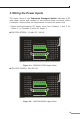
IGS-5225-8T2S2X:12~48VDC,24VAC
Input DC 12V~48V
AC 24V
DC1 DC2
Fault
1A@24V
DI1 DO0 DO1DI0 GNDGND
1 2 3 4 5 6
1 2 3 4 5 6
Figure 3-1: IGS-5225-8T2S2X Upper Panel
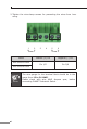
IGS-5225-8P2S2X:48~56VDC
Input DC 48-56V
DI0 DI1 DO0 DO1 GND GND
DC1
+
DC2Fault
+
1A@24V
1 2 3 4 5 6
1 2 3 4 5 6
Figure 3-2: IGS-5225-8P2S2X Upper Panel