
Quick Guide


5
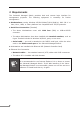
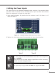
3. Wiring the Power Inputs
The Upper Panel of the Industrial Managed Switch consists of one terminal block
connectorwithin6contacts for tworedundantpower inputs andfaultalarm. Please
followthestepsbelowtoinsertthepowerwire.
1.Insert positive/negative DC power wires into contacts 1 and 2 for Power 1 or 5
and6forPower2.
Fault
V1+ V2+
PWR2PWR1
Max. fault loading: 24V, 1A
DC Input: 12-48V , 1.5A max.
AC
Input: 24V , 1A max.
1 2 3 4 5 6
Figure 3-1: Industrial Managed Switch Inlet Power Socket
2.Tightenthewire-clampscrewsforpreventingthewiresfromloosening.
1 2 3 4 5 6
V1+ V1- V2+ V2-
Power 1 Power 2
Note
The wire gauge for the terminal blockshould be in the range from
12 to 24 AWG.
Pleasecheck thewire AWGAmpere specificationbeforeconnecting
PLANETIndustrialManagedSwitch.
Note
The power input range is DC 12~48VandsupportsAC 24V.