
IFB-244-Series User Manual

7
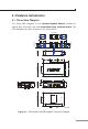
4 Hardware Introduction
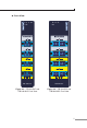
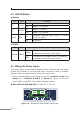
4.1 Three-View Diagram
The three-view diagram of the Optical Bypass Switch consists of
opticalberconnector andoneremovable 6-pin terminal block. The
LED indicators are also located on the front panel.
Top View
Side View Front View
Mounting Kit
Mounting Kit
DIN-Rail Kit
Side View Rear View
Unit: mm
32.00
135.00
87.80
97.10
48.8046.50 39.70
28.00
48.80
53.50 53.50
18.00
15.20
40.00
9.20
40.00
28.0018.00
28.00
18.0028.00
28.00
40.00
28.00
P1 P2 Fault
Normal
Remote Network
Local Switch
IFB-244-SLC
TX RX
A
TX RX
B
TX RX
A
TX RX
B
Max. fault loading: 24V, 1A
DC Input: 9-48V
, 0.5A max.
AC Input: 24V
, 0.2A max.
V1+ V2+
PWR1
PWR2Fault
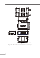
Figure 4-1: IFB-244-SLC and IFB-244-MLC Three-View Diagram