
IFB-244-Series User Manual

11
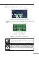
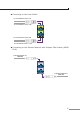
IFB-244-SSC/IFB-244-MSC: 9~48V DC or 24V AC
1 2 3 4 5 6
Max. fault loading: 24V, 1A
V1+
V2+
PWR1
PWR2Fault
DC Input: 9-48V , 0.5A max.
AC Input: 24V
, 0.2A max.
Figure 4-6: IFB-244-SSC/IFB-244-MSC upper panel
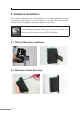
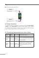
2. Tighten the wire-clamp screws for preventing the wires from loos-
ening.
1 2 3 4 5 6
V1+ V1- V2+ V2-
Power 1 Fault Power 2
Figure 4-7: PWR1 & PWR2 pins of terminal block.
Note
The wire gauge for the terminal block should be in the
range from 12 to 24 AWG.
When performing any of the procedures like inserting
the wires or tightening the wire-clamp screws, make
sure the power is OFF to prevent from getting an electric
shock.