
IFB-244-Series User Manual

10
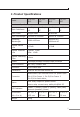
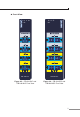
4.2 LED Denition
System
LED Color Function
P1 Green
Lit: Power 1 is active.
O: Power 1 is inactive.
P2 Green
Lit: Power 2 is active.
O: Power 2 is inactive.
FAULT Red
Lit:
Hardware indicates either Power 1 or Power
2 has no power.
O: No failure.
STATE
LED Color Function
Normal Green
Lights:
To indicate the Bypass Switch is operating
in Normal mode with power input.
O:
To indicate the Bypass Switch is operating
in Bypass mode with power failure.
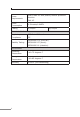
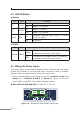
4.3 Wiring the Power Inputs
The upper panel of the Optical Bypass Switch indicates an inlet power
socket and consists of one terminal block connector within 6 contacts.
Please follow the steps below to insert the power wire.
1. Insert positive/negative DC power wires into Contacts 1 and 2 for
Power 1, or Contacts 5 and 6 for Power 2. Figure 4-5 and 4-6
show PWR1 and PWR2 of the Optical Bypass Switch.
IFB-244-SLC/IFB-244-MLC: 9~48V DC or 24V AC
Max. fault loading: 24V, 1A
DC Input: 9-48V
, 0.5A max.
AC Input: 24V
, 0.2A max.
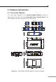
V1+ V2+
PWR1
PWR2Fault
1 2 3 4 5 6
Figure 4-5: IFB-244-SLC/IFB-244-MLC upper panel