Industrial 2-channel Optical Fiber Bypass Switch IFB-244 Series User’s Manual
Table of Contents 1. Package Contents....................................................................... 3 2. Product Features........................................................................ 4 3. Product Specifications................................................................. 5 4 Hardware Introduction................................................................ 7 4.1 Three-View Diagram............................................................ 7 4.2 LED Definition...................
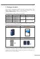
1. Package Contents Thank you for purchasing PLANET Industrial 2-channel Optical Fiber Bypass Switch, IFB-244 Series. In the following section, the term “Optical Bypass Switch” means the IFB-244 Series.
2.
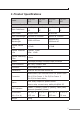
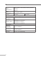
3. Product Specifications Model IFB-244SLC IFB-244SSC IFB-244MLC IFB-244MSC Hardware Specifications Optic Interfaces 4 x Duplex 4 x Duplex 4 x Duplex 4 x Duplex LC SC LC SC Optic Mode Single Mode Multimode Optic Wavelength 1310nm & 1550nm 850nm & 1300nm Operating Wavelength 1260~1620nm 850nm±40 / 1300nm±40 Bypass Return Loss >50dB >35dB Bypass Insertion Loss Typical: 1.0dB Max: 1.
Power Requirements Dual 9-48V DC with polarity reverse protection function 24V AC Power Consumption 0.54 watts/1.
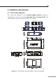
4 Hardware Introduction 4.1 Three-View Diagram The three-view diagram of the Optical Bypass Switch consists of optical fiber connector and one removable 6-pin terminal block. The LED indicators are also located on the front panel. DIN-Rail Kit 28.00 40.00 48.80 28.00 28.00 18.00 28.00 53.50 Rear View 53.50 18.00 28.00 18.00 48.80 39.70 Side View 46.50 97.10 87.80 PWR1 PWR2 DC Input: 9-48V , 0.5A max. AC Input: 24V , 0.2A max.
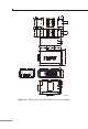
28.00 40.00 50.00 18.00 28.00 40.00 50.00 18.00 53.50 53.50 18.00 46.50 48.80 39.70 97.10 87.80 P1 IFB-244-SSC RX Local Switch B TX RX A TX RX B TX A TX Remote Network V2+ V1+ PWR1 50.00 Normal P2 Fault Max. fault loading: 24V, 1A RX 135.00 87.80 Fault PWR2 DC Input: 9-48V , 0.5A max. AC Input: 24V , 0.2A max. 107.00 33.55 18.
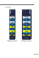
Front View P1 P2 Fault Normal P1 P2 Remote Network Remote Network A TX A RX TX RX TX RX TX RX TX B TX RX A B TX RX B A TX Fault Normal RX B RX Local Switch Local Switch IFB-244-SLC IFB-244-SSC Figure 4-3: IFB-244-SLC and IFB-244-MLC Front View Figure 4-4: IFB-244-SSC and IFB-244-MSC Front View 9
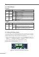
4.2 LED Definition System LED P1 P2 FAULT Color Green Green Red Function Lit: Power 1 is active. Off: Power 1 is inactive. Lit: Power 2 is active. Off: Power 2 is inactive. Lit: Hardware indicates either Power 1 or Power 2 has no power. Off: No failure. STATE LED Color Function Lights: To indicate the Bypass Switch is operating in Normal mode with power input. Off: To indicate the Bypass Switch is operating in Bypass mode with power failure. Normal Green 4.
IFB-244-SSC/IFB-244-MSC: 9~48V DC or 24V AC Max. fault loading: 24V, 1A 1 2 3 4 5 6 V2+ V1+ PWR1 Fault PWR2 DC Input: 9-48V , 0.5A max. AC Input: 24V , 0.2A max. Figure 4-6: IFB-244-SSC/IFB-244-MSC upper panel 2. Tighten the wire-clamp screws for preventing the wires from loosening. 1 2 3 4 V1+ V1Power 1 5 6 V2+ V2Fault Power 2 Figure 4-7: PWR1 & PWR2 pins of terminal block. Note The wire gauge for the terminal block should be in the range from 12 to 24 AWG.
5. Hardware Installation This section describes the functionalities of the Optical Bypass Switch’s components and guides you to installing it on the DIN rail and wall. Please read this chapter completely before continuing. This following pictures guide you to how to install the device, and the device is not IFB-244 Series. Note 5.1 DIN-rail Mounting Installation 1 2 5.
5.3 Side Wall-mount Plate Mounting 5.4 Grounding the Device Uses MUST complete grounding wired with the device; otherwise, a sudden lightning could cause fatal damage to the device. EMD (Lightning) DAMAGE IS NOT CONVERED UNDER WARRANTY.
6. Optical Fiber and Power Connections 6.1 Optical Fiber Connection The IFB-244 series is equipped with a total of 4 duplex fiber connectors and they are separated into two groups – Remote Network channels and Local Switch channels. Remote Network A TX RX B TX RX Remote Network group has 2 fiber channels that are used to connect to the other two remote fiber Ethernet switches. A TX RX B TX RX Local Switch group has 2 fiber channels that are used to connect to the local fiber Ethernet switch.
Connecting to the Local Switch To Local Switch C Port 1’s TX B TX RX To Local Switch C Port 1’s RX A TX RX B TX RX Local Switch To Local Switch C Port 2’s RX IFB-244-SLC To Local Switch C Port 2 ’s TX Connecting to the Remote Network with Simplex Fiber Cables (WDM/ Bi-di) To Remote Switch A’s WDM SFP P1 P2 Fault Normal Remote Network A TX RX B TX RX A TX RX To Remote Switch B’s WDM SFP 15
Connecting to the Local Switch To Local Switch C Port 1’s WDM SFP B TX RX A TX RX B TX RX Local Switch To Local Switch C Port 2’s WDM SFP IFB-244-SLC 6.2 Power Connection The IFB-244 Series is expected to be powered from the same power source as the Local Switch to ensure power system failure makes the IFB-244 Series change to Bypass mode. Make the IFB-244 Series share the same power source as the Local Switch. 6.
Normal Mode Power Power good P1 Ring P2 FAULT P1 R.O. P2 P1 Fault Ring Normal RESET P2 FAULT R.O.
Bypass Mode Power Power failed P1 Ring P2 FAULT P1 R.O. P2 P1 Fault Ring Normal RESET 115200,N,8,1 1000 LNK/ACT Link good 6 1 Remote Network 1000 LNK/ACT A TX RX 6 2 B TX 5 RX 100 LNK/ACT Link good 5 100 LNK/ACT 4 Link failed A TX 4 RX 3 3 B TX Link failed RX 2 2 1000 LNK/ACT Local Switch 1000 LNK/ACT IFB-244-SLC 10/100 LNK/ACT 1 1 10/100 LNK/ACT Switch A IFB-244 Series Optical Bypass Switch Power failed P1 Ring P2 FAULT R.O.
Customer Support Thank you for purchasing PLANET products. You can browse our online FAQ resource on PLANET web site first to check if it could solve your issue. If you need more support information, please contact PLANET switch support team. PLANET online FAQs: http://www.planet.com.tw/en/support/faq.php Switch support team mail address: support @planet.com.tw Copyright © PLANET Technology Corp. 2019. Contents are subject to revision without prior notice.
EC Declaration of Conformity For the following equipment: *Type of Product : Industrial 2-channel Optical Fiber Bypass Switch *Model Number : IFB-244-SLC, IFB-244-MLC, IFB-244-SSC, IFB-244-MSC * Produced by: Manufacturer‘s Name : Planet Technology Corp. Manufacturer‘s Address : 10F., No.96, Minquan Rd., Xindian Dist., New Taipei City 231, Taiwan R.O.C.