User’s Manual of ICS-11x Serial Device Server Series RS232/RS422/RS485 Serial Device Server ICS-110 / ICS-115A/ ICS-120 1
User’s Manual of ICS-11x Serial Device Server Series Trademarks Copyright © PLANET Technology Corp. 2020. Contents are subject to revision without prior notice. PLANET is a registered trademark of PLANET Technology Corp. All other trademarks belong to their respective owners.
User’s Manual of ICS-11x Serial Device Server Series TABLE OF CONTENTS 1. INTRODUCTION .................................................................................................................... 5 1.1 Packet Contents ............................................................................................................................................. 5 1.2 Product Description .....................................................................................................................
User’s Manual of ICS-11x Serial Device Server Series 4.2.4 Time........................................................................................................................................................................... 39 4.2.5 Console ..................................................................................................................................................................... 40 4.3 Accessible IP ........................................................................
User’s Manual of ICS-11x Serial Device Server Series 1. INTRODUCTION Thank you for purchasing PLANET ICS-110/ICS-115A/ ICS-120 Serial Device Server. “Serial Server” is used as an alternative name in this User's Manual. ICS-110 1-Port RS232/422/485 Serial Device Server ICS-115A 1-Port RS232/422/485 Serial Device Server with 1-Port 100BASE-FX SFP ICS-120 2-Port RS232/422/485 Serial Device Server “Serial Server” mentioned in this Guide refers to the ICS-110/ICS-115A/ ICS-120. 1.
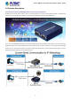
User’s Manual of ICS-11x Serial Device Server Series 1.2 Product Description Cost-effective Solution for RS232/422/485 Serial-to-Ethernet Application PLANET ICS-11x Serial Device Server series is specially designed to convert one/two RS232, RS422 or RS485 serial communication to Fast Ethernet networking to extend the network distance efficiently and inexpensively.
User’s Manual of ICS-11x Serial Device Server Series Extending Distance (Only ICS-115A) The ICS-115A is able to extend the distance of deploying serial equipment and hosts. The selectable fiber-optic cables on the basis of distance are provided. Therefore, this product will perfectly satisfy the diverse demands while providing reliable and efficient network solutions based on the distance and budgets of installation.
User’s Manual of ICS-11x Serial Device Server Series 8
User’s Manual of ICS-11x Serial Device Server Series 1.3 How to Use This Manual This User’s Manual is structured as follows: Section 2, INSTALLATION It explains the functions of the ICS-11x Series and how to physically install the ICS-11x Series. Section 3, SERIAL DEVICE SERVER MANAGEMENT The chapter explains how to manage the ICS-11x Series in different ways. Section 4, WEB CONFIGURATION It describes how to configure by web interface.
User’s Manual of ICS-11x Serial Device Server Series 1.
User’s Manual of ICS-11x Serial Device Server Series 1.5 Product Specifications Product ICS-110 ICS-115A ICS-120 Serial Interface Serial Port 1 x DB9 male Serial Standards RS232/RS422/4-wire RS485/2-wire RS485 Baud Rate (Data Rate) 50bps to 921Kbps Data Bits 5, 6, 7, 8 Stop Bit 1, 1.
User’s Manual of ICS-11x Serial Device Server Series Management Web management Telnet Console management Management Interfaces Windows-based VCOM Utility management SNMPv1, v2c / SNMP Trap UNI-NMS monitoring PLANET Smart Discovery Utility IP Version IPv4 and IPv6 TCP Server / TCP Client UDP Client Virtual COM Operation Mode RFC2217 Telnet Server Pair Connection – Remote (Slave) Pair Connection – Local (Master) Modbus converter server / client Windows-based Only: Windows XP Windows Server 2003 Virtual
User’s Manual of ICS-11x Serial Device Server Series RFC 3315 DHCPv6 Client RFC 3513 IPv6 Addressing Architecture RFC 4443 ICMPv6 EIA/TIA RS232/422/485 Regulatory Approval Compatible Media Converter Chassis Note.
User’s Manual of ICS-11x Serial Device Server Series 2. INSTALLATION This section describes the hardware features and installation of the Serial Servers' components on the desktop or rack. For easier management and control of the Serial Servers, familiarize yourself with its display indicators, and ports. Front panel illustrations in this chapter display the LED indicators. Before connecting any network device to the Serial Servers, please read this chapter completely. 2.1 Hardware Description 2.1.
User’s Manual of ICS-11x Serial Device Server Series ICS-115A: 94 x 70 x 26mm (W x D x H) 15
User’s Manual of ICS-11x Serial Device Server Series ICS-120: 94 x 70 x 26mm (W x D x H) 16
User’s Manual of ICS-11x Serial Device Server Series 2.1.2 Front / Top Panel The front panels of the Serial Servers are shown in Figure 2-1-1. ICS-110 ICS-115A ICS-120 Figure 2-1-1: Front Panels of Serial Servers The top panel of the ICS-120 is shown in Figure 2-1-2. ICS-120 Figure 2-1-2: Top Panel of ICS-120 Fast TP/ SFP interface 10/100BASE-TX copper, RJ45 twisted-pair: Up to 100 meters. 100BASE-FX SFP interface, Up to 2km~120km, vary on SFP modules.
User’s Manual of ICS-11x Serial Device Server Series 2.1.3 LED Indications The front/top panel LEDs indicate the instant status of power and system status, port links and data activity; they help monitor and troubleshoot when needed. System LED Color PWR Green Lights Power is activated.
User’s Manual of ICS-11x Serial Device Server Series Reset button On the rear panel, the reset button is designed for rebooting the system. The following is the summary table of the reset button functions: Reset Button Reset Button Pressed and Released Function < 5 sec: System reboot Reboot the Serial Server Reset the Serial Server to Factory Default configuration. The Serial Server will then reboot and load the default settings as shown below: System Reset > 5 sec: Factory default 2.1.
User’s Manual of ICS-11x Serial Device Server Series 2.1.
User’s Manual of ICS-11x Serial Device Server Series 2.2 Installing the Serial Server This section describes how to install your Serial Server and make connections to the Serial Server. Please read the following section and perform the procedure in the order being presented. To install your Serial Server on a desktop or rack, simply complete the following steps. 2.2.1 Installation Steps 1. Unpack the Serial Server 2. Check if the DIN-rail bracket is screwed on the Serial Server or not.
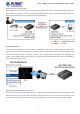
User’s Manual of ICS-11x Serial Device Server Series 2.2.2 Wall-mount Installation Step 1: Please find the wall that can mount the Serial Server Step 2: Screw two screws on the wall. Step 3: Hang the Serial Server on the screws from the wall. Step 4: Refer to Chapter 2.1.5 Power Information on power supply to the Serial Server . Before mounting the device to the wall, please check the location of the electrical outlet and the length of the Ethernet cable.
User’s Manual of ICS-11x Serial Device Server Series 2.2.3 Media Chassis Installation (ICS-110/115A) To install the Serial Server in a 10-inch or 19-inch standard rack, follow the instructions described below. Step 1: Place your Serial Server on a hard flat surface, with the front panel positioned towards your front side. Step 2: Carefully slide in the module until it is fully and firmly fitted into the slot of the chassis; the Power LED of the Serial Server will turn ON.
User’s Manual of ICS-11x Serial Device Server Series Step 2: Now slide the DIN rail into the track. Step 3: Check whether the DIN rail is tightly on the track. You must use the screws supplied with the mounting brackets. Damage caused to the parts by using incorrect screws would invalidate your warranty.
User’s Manual of ICS-11x Serial Device Server Series 3. SERIAL DEVICE SERVER MANAGEMENT This chapter covers the following topics as to how to manage the Serial Server: Requirements Web Management Remote Management PLANET Smart Discovery Utility 3.1 Requirements Workstations running Windows 2000/XP, 2003, Vista/7/8/10, 2008, MAC OS9 or later, or Linux, UNIX , or other platforms compatible with TCP/IP protocols.
User’s Manual of ICS-11x Serial Device Server Series 3.2 Web Management The Serial Server offers management features that allow users to manage the Serial Server from anywhere on the network through a standard browser such as Microsoft Internet Explorer. After you set up your IP address for the switch, you can access the Serial Server's Web interface applications directly in your Web browser by entering the IP address of the Serial Server. For example, the default IP address of the Serial Server is 192.
User’s Manual of ICS-11x Serial Device Server Series 4. After entering the password, the main screen appears as shown in Figure 3-2-3. Figure 3-2-3: Web Main Screen of Serial Server 5. The Main Menu in the middle of the Web page lets you access all the functions and statuses. It appears as shown in Figure 3-2-4. Figure 3-2-4: Main menu Now, you can use the Web management interface to continue the Serial Server management. Please refer to the user manual for more. 1.
User’s Manual of ICS-11x Serial Device Server Series 3.3 Remote Management The Serial Server also supports Telnet for remote management. You can use Telnet to open a terminal session over one of the Ethernet ports. The Serial Server asks for user name and password for remote login when using Telnet; please use the following default IP address, username and password for the first-time login. Default IP Address: 192.168.0.
User’s Manual of ICS-11x Serial Device Server Series 3.4 PLANET Smart Discovery Utility For easily listing the Serial Server in your Ethernet environment, the Planet Smart Discovery Utility is an ideal solution. The following installation instructions are to guide you to running the Planet Smart Discovery Utility. 1. Download the Planet Smart Discovery Utility from the administrator PC. 2. Run this utility as the following screen appears.
User’s Manual of ICS-11x Serial Device Server Series 2. After setup is completed, press the “Update Device”, “Update Multi” or “Update All” button to take effect. The functions of the 3 buttons above are shown below: Update Device: Use current setting on one single device. Update Multi: Use current setting on multi-devices. Update All: Use current setting on whole devices in the list. The same functions mentioned above also can be found in “Option” tools bar. 3.
User’s Manual of ICS-11x Serial Device Server Series 4. WEB CONFIGURATION This section introduces the configuration and functions of the Web-based management from Serial Server. About Web-based Management The Serial Server offers management features that allow users to manage the Serial Server from anywhere on the network through a standard browser such as Microsoft Internet Explorer. The Web-based Management supports Internet Explorer 7.0.
User’s Manual of ICS-11x Serial Device Server Series 1. Logging on to the Serial Server Use Internet Explorer 7.0 or above Web browser. Enter the factory default IP address to access the Web interface. The factory default IP address is shown as follows: Default IP Address: 192.168.0.100 Default Username: admin Default Password: admin 2.
User’s Manual of ICS-11x Serial Device Server Series Now, you can use the Web management interface to continue the switch management or manage the Serial Server by Web interface.
User’s Manual of ICS-11x Serial Device Server Series 4.1 Main Web Page The Serial Server provides a Web-based browser interface for configuring and managing it. This interface allows you to access the Serial Server using the Web browser of your choice. The main web page is shown in Figure 4-1-4 Figure 4-1-4: Web Main Page Main Menu Via the Web Management, the administrator can set up the Serial Server by selecting the functions that are listed in the Main Function. The screen in Figure 4-1-5 appears.
User’s Manual of ICS-11x Serial Device Server Series • Save and Restart Save the configuration and reboot device. • Refresh the page Log out the Serial Server.
User’s Manual of ICS-11x Serial Device Server Series 4.2 System Use the System menu items to display and configure basic administrative details of the Serial Server. Under the System, the following topics are provided to configure and view the system information. This section has the following items: System The Serial Server system information is provided here. Port This page displays status of each port. Device Configure device name and syslog server on this page.
User’s Manual of ICS-11x Serial Device Server Series IPv4 Configuration Object Description • IP Configuration The status of IPv4 configuration. • IP Address The current IPv4 address of the device. • Subnet Mask The current IPv4 subnet mask of the device. • Gateway The current IPv4 gateway of the device. • Primary DNS The current first DNS server of the device. • Second DNS The current second DNS server of the device. • MAC Address Specifies the device MAC address.
User’s Manual of ICS-11x Serial Device Server Series 4.2.2 Port This Port page displays the status of each port, including operation mode and serial settings. The screen in Figure 4-2-2 appears. Figure 4-2-2: Port Status Page Screenshot The following column shows the Port statuses: Object Description • No. The serial number (No.) indicates port number. It can be directly linked to the corresponding page settings. • Operation Mode The current operation mode of serial server.
User’s Manual of ICS-11x Serial Device Server Series 4.2.3 Device This page provides configuration of device name and syslog server. The screen in Figure 4-2-3 appears. Figure 4-2-3: Device Setup Page Screenshot The page includes the following fields: Object Description • Server Name To configure the name of server. The default value is Server. • Syslog Server To configure IP address of syslog server.
User’s Manual of ICS-11x Serial Device Server Series 4.2.5 Console This page is to configure management methods for web and remote console. The screen in Figure 4-2-5 appears. Figure 4-2-5: Console Setup Page Screenshot The page includes the following fields: Object Description • Web Console To enable or disable access to the web console. The default is Enable. • Remote Console To enable or disable access to the remote console. The default is Enable.
User’s Manual of ICS-11x Serial Device Server Series 4.3 Accessible IP This page provides the specified IP address to connect with serial server. When the list of accessible IP is enabled, only IP address in the list can connect to device. When the function is disabled, there is no such restriction. List allows user to configure up to four IP groups. The accessible IP setup screen in Figure 4-3-1 appears.
User’s Manual of ICS-11x Serial Device Server Series 4.4 Network This page allows the user to configure IPv4 or IPv6 address. The IP configuration screen in Figure 4-4-1 appears. Figure 4-4-1: IP Configuration Page Screenshot The page includes the following fields: IPv4 Object Description • IP Configuration Configure static or DHCP to get IPv4 address. The default value is static.
User’s Manual of ICS-11x Serial Device Server Series • Prefix The IPv6 network mask, in number of bits (prefix length). The default value is 64. • Gateway The default gateway for the IPv6 interface. • Primary DNS Configure the first DNS server. • Second DNS Configure the second DNS server.
User’s Manual of ICS-11x Serial Device Server Series 4.5 Port Config The following figure shows port settings. Note that these settings need to match the parameters on serial port of the serial device. Each parameter is described in details in the following section. The port configuration screen in Figure 4-5-1 appears.
User’s Manual of ICS-11x Serial Device Server Series 4.5.1 Serial setup The serial setup screen is shown in Figure 4-5-2. Figure 4-5-2: Serial Setup Page Screenshot Object Description • Description Used to distinguish the name of each serial port. It allows 1 to 15 characters (e.g. A-Z, a-z, 0-9) • Baud Rate The rate of data transmission to and from the attached serial device. It allows 50 bps to 921600 bps. The default is 921600 bps.
User’s Manual of ICS-11x Serial Device Server Series 4.5.2 Operation mode The serial server makes connected Serial equipment become IP-based. That also makes them able to connect to a TCP/IP networking immediately. The serial server allows traditional Computer/Client COM ports access to a serial equipment anywhere on the Ethernet LAN network.
User’s Manual of ICS-11x Serial Device Server Series 4.5.2.2 Remote Pair Master/Slave mode When a device connected to an serial server can be transparently connected to another device on serial server; data and modem control signals are exchanged. This protocol can overcome the limitations of traditional serial communication distances and introduce many new usability and feasibility for serial device control. In short, Remote Pair-Master/Slave mode provides tunnel-like functionality over the network.
User’s Manual of ICS-11x Serial Device Server Series The remote pair slave mode screenshot in Figure 4-5-7 appears. Figure 4-5-7: Remote Pair Slave Mode Screenshot The page includes the following fields: Object Description • TCP Keep-alive TCP keep alive interval shows how many seconds the unit waits during an inactive Interval connection before checking its status. If the unit does not receive a response, it will drop that connection. The default is 0 minute.
User’s Manual of ICS-11x Serial Device Server Series 4.5.2.3 RF2217 mode RS232 to Ethernet Connector allows to choose the transmission protocol, supporting connections using either the RAW data transmission algorithm or the Telnet (RFC 2217) protocol.Therefore, Telnet can act as an interface to a network device server connected to a remote serial device. The RF2217 mode screenshot in Figure 4-5-8 appears.
User’s Manual of ICS-11x Serial Device Server Series 4.5.2.4 Serial Telnet mode Telnet (TELecommunication NETwork) is a network protocol used on the Internet or local area network (LAN) connections. The Telnet protocol type is the correct setting for most servers and serial devices, such as Managed Ethernet switches or Gateways. In the case of a Telnet session, the process is reversed, where the connected server reads and writes data to RS-232 serial port.
User’s Manual of ICS-11x Serial Device Server Series Example: Use Putty TCP/IP Winsock mode PuTTY is a free implementation of Telnet and SSH for Win32 and Unix platforms, along with an xterm terminal emulator. In this case we use PuTTY to connect GS-5220-24P4XV managed switch via ICS-110. Figure 4-5-11: Serial Telnet Mode Application ICS-110 1. Set Port Configuration as shown below. Figure 4-5-12: Port Configuration 2. Set operation mode as Serial Telnet mode. 3.
User’s Manual of ICS-11x Serial Device Server Series 5. Then it can connect to switch successfully.
User’s Manual of ICS-11x Serial Device Server Series 4.5.2.5 TCP Server mode When the serial server is configured as a TCP server, it waits for a connection initiated by another network device. User must set the local TCP port number for which it will listen for the connection, and the serial server provides the maximum number of two concurrent connections. Incidentally, serial server can be configured as a client or server. The TCP server mode topology in Figure 4-5-115 appears.
User’s Manual of ICS-11x Serial Device Server Series • Separator If the Separator is enabled, the serial receive character port will be discarded until the start separator is detected on the serial port. When the end separator is received, the buffered characters, including the start and end separators, are sent to the network. The range of value is from 0 to FF. The default is disable. • Separator Process Separators are ASCII characters specified by the user when configuring the serial serve.
User’s Manual of ICS-11x Serial Device Server Series Figure 4-5-19: TCP Server Mode Configuration 3. Run the modbus master application (e.g. Modbus Poll) and set parameters as shown below. Figure 4-5-20: Modbus application Configuration 4. Modbus master application (e.g. Modbus Poll) reads data from modbus sensor susecssfully.
User’s Manual of ICS-11x Serial Device Server Series 4.5.2.6 TCP Client mode The TCP client initiates a connection to the server on the network. You must set up the target IP address and assigned local port number of server that you want the client to communicate with. In the data transmission phase, the data is transmitted to the destination in the order to which they are sent. SERIAL SERVER device supports four sets of sequential connections. The TCP client mode topology in Figure 4-5-22 appears.
User’s Manual of ICS-11x Serial Device Server Series port 1, 5005 for port 2, 5006 for port 3 and , 5007 for port 4. • Frame Length This parameter can be used to control the data packet. When the device port is in the buffer until the specified data is accumulated, the data will be packed and transmitted by the network. This parameter is 0 to indicate that the data will not be packed until the buffer is full. The range of value is from 0 to 1024. The default is 0.
User’s Manual of ICS-11x Serial Device Server Series 4.5.2.7 UDP mode UDP is a Connectionless of the non-reliable transmission protocol; it does not need to verify information and does not guarantee correctness for some of the larger amount of information. The reliability is greater than the reliability of transmission which is a good choice. UDP mode can allocate up to four ranges of IP. Each network output data is copied and sent to each IP for each range. The UDP mode topology in Figure 4-5-24 appears.
User’s Manual of ICS-11x Serial Device Server Series • Separator Process Separators are ASCII characters specified by the user when configuring the serial serve. This parameter describes how to control characters received on a serial port are sent across the network. The default is Do nothing. Do nothing: it will pack the accumulated data including Separators. Strip Separator: it controls striping of Separator from the received characters before the received characters are sent to the network.
User’s Manual of ICS-11x Serial Device Server Series 4.5.2.8 Virtual COM mode VCOM mode functionality provides a virtual-local COM port for Windows systems. The VCOM driver should be installed on the PC through the VCOM Administration Utility. The driver establishes a TCP connection to the connected serial device by mapping the local serial port to the IP port of the device port. VCOM mode also supports up to 256 mirroring ports at the same time, but must be in accordance with the computer resources.
User’s Manual of ICS-11x Serial Device Server Series Do nothing: it will pack the accumulated data including Separators. Strip Separator: it controls striping of Separator from the received characters before the received characters are sent to the network. • Separator Time Out Separator timeout controls the maximum amount of time that can be used to buffer characters before the characters are sent to the network.
User’s Manual of ICS-11x Serial Device Server Series 3. Run VCOM software to set port mapping. Port 1 is related to COM4 port. Figure 4-5-31: VCOM Software 4. Run the modbus master application (e.g. Modbus Poll) and set parameters as shown below. Figure 4-5-32: Modbus application Configuration 5. Modbus master application (e.g. Modbus Poll) reads data from modbus sensor susecssfully.
User’s Manual of ICS-11x Serial Device Server Series 4.5.2.9 Modbus Converter Server mode The ICS Serial devices support standard Modbus protocol and various hardware interfaces (serial and Ethernet). Modbus TCP and RTU can be used to convert the Modbus protocol. The Modbus master can communicate with the serial network of devices connected to the serial port of the server converter via a server converter.
User’s Manual of ICS-11x Serial Device Server Series 4.5.2.10 Modbus Converter Client mode The ICS Serial devices support standard Modbus protocol and various hardware interfaces (serial and Ethernet). Modbus TCP and RTU can be used to convert the Modbus protocol. The Modbus master can communicate with the serial network of devices connected to the serial port of the server converter via a server converter.
User’s Manual of ICS-11x Serial Device Server Series Connection Target IP address Object Description • Target IP address 1 IP addresses are used to deliver packets of data across a network and have what is through 4 termed end-to-end significance. The network data is sent to the device in a first-in, first-out (FIFO) method. During data transfer phase, data is transmitted sequentially through established path-arriving at the destination in the order in which it was sent.
User’s Manual of ICS-11x Serial Device Server Series 4.6 SNMP Setup Use the Port Menu to display or configure the Serial Server's ports. This section includes the page that displays current port configurations. Ports can also be configured here. The Port Configuration screen in Figure 4-6-1 appears. Figure 4-6-1: SNMP Setup page Screenshot The page includes the following fields: Object Description • SNMP Active Indicates the SNMP mode operation.
User’s Manual of ICS-11x Serial Device Server Series 4.7 Maintenance Use the Port Menu to display or configure the Serial Server's ports. This section includes the page that displays current port configurations. Ports can also be configured here. 4.7.1 Change Password After logging in to the serial server, user can make changes from the "Change Password" page. The Change Password screen in Figure 4-7-1 appears.
User’s Manual of ICS-11x Serial Device Server Series 4.7.3 Firmware Update This page facilitates an update of the firmware controlling the switch. The Firmware Update screen in Figure 4-7-3 appears. Figure 4-7-3: Firmware Update Page Screenshot To open Firmware Update screen, perform the following: 1. Click Maintence -> Firmware Update. 2. The Firmware Update screen is displayed as in Figure 4-7-3. 3. Click the “ 4. Select on the firmware, then click “ 5.
User’s Manual of ICS-11x Serial Device Server Series 4.8 Save and Restart When applying any configuration changes of serial server, it’s required to save changed configuration and reboot system. Therefore the new configuration will be applied after rebooting. The Save and Restart screen in Figure 4-8-1 appears. Figure 4-8-1 : Save and Restart Page Screenshot Buttons : Click to save changes and restart ststem.
User’s Manual of ICS-11x Serial Device Server Series 5. SOFTWARE VCOM UTILITY The serial server provides VCOM software to manage serial devices. With VCOM software, it’s easy to install and configure serial server over the network. It also supports central management to manage multiple serial servers from one site. Two function groups are provided and they are easy to use for searching device and creating virtual COM to view via the console port.
User’s Manual of ICS-11x Serial Device Server Series 3. The setup wizard will show the progress of the installation and status as shown in Figure 5-1-3. Figure 5-1-3 : Installing Process 4. Click Finish to successfully complete installation of VCOM software.as shown in Figure 5-1-4. Figure 5-1-4 : Installation Finished 5. Restart computer as shown in Figure 5-1-5.
User’s Manual of ICS-11x Serial Device Server Series 5.2 Search Devices 1. First click "Add Device" and then click "Search", if device has access to network, as shown in Figure 5-2-1. Figure 5-2-1 : Searching Devices 2. After adding an ICS-110 device as shown in Figure Figure 5-2-2.
User’s Manual of ICS-11x Serial Device Server Series 5.3 COM Port Mapping This function should be set as VCOM mode on the serial server. VCOM software will create the corresponding virtual COM ports for com port mapping as shown in Figure 5-3-1. Figure 5-3-1 : VCOM software Add Virtual COM port 1. Click "Search" to search the network for device servers. 2. Once a server has been found, select it to add it to the COM mapping list and Click "OK" to take effect as shown in Figure 5-3-2.
User’s Manual of ICS-11x Serial Device Server Series 4. From the Windows Device Manager, four COM Ports are added to the device list as shown in Figure 5-3-4.