
Quick Guide


8
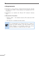
3.4 Wiring the Power Inputs
The 6-contact terminal block connector on the top panel of Cellular
Gateway is used for two redundant power inputs. Please follow the
steps below to insert the power wire.
Caution
When performing any of the procedures like inserting the
wires or tightening the wire-clamp screws, make sure the
power is OFF to prevent from getting an electric shock.
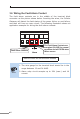
1. Insert positive and negative DC power wires into contacts 1 and 2
for POWER 1, or 5 and 6 for POWER 2.
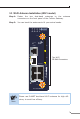
Max. Fault Alarm Loading: 24V, 1A
DI1 DO0 DO1DI0 GNDGND
ANT1 ANT3
ANT2
Cellular
ANT4
V1+ V2+
PWR1
PWR2Alarm
DC Input: 9-54V
, 1.5A max.
AC Input: 24V
, 1A max.
1 2 3 4 5 6
1 2 3 4 5 6
Note
Please make sure the input voltage is under the specifica-
tions of the Cellular Gateway.