Industrial 5G NR Cellular Gateway ICG-2515 Series Quick Installation Guide
Table of Contents 1. Package Contents....................................................................... 3 2. Requirements............................................................................. 4 3. Hardware Installation.................................................................. 5 3.1 SIM Card Installation........................................................... 5 3.2 5G NR Antenna Installation.................................................. 6 3.
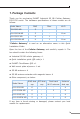
1. Package Contents Thank you for purchasing PLANET Industrial 5G NR Cellular Gateway, ICG-2515 series. The hardware specifications of these models are as follows: Model Name RJ45 Fiber Wi-Fi ICG-2515-NR 5 - - ICG-2515W-NR 5 - 11ax ICG-2515F-NR 4 1 - ICG-2515FW-NR 4 1 11ax “Cellular Gateway” is used as an alternative name in this Quick Installation Guide. Open the box of the Cellular Gateway and carefully unpack it.
2. Requirements zz Workstations running Windows 10/XP/2003/Vista/7/8/2008, MAC OS X or later, Linux, UNIX, or other platforms are compatible with TCP/ IP protocols. zz Workstations are installed with Ethernet NIC (Network Interface Card). zz Ethernet Port Connection Network cables -- Use standard network (UTP) cables with RJ45 connectors. The above PC is installed with Web browser. Note 4 It is recommended to use Chrome 98.0.xxx or above to access the Cellular Gateway.
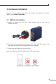
3. Hardware Installation Refer to the illustration and follow the simple steps below to quickly install your Cellular Gateway. 3.1 SIM Card Installation A. Insert an ejector pin into the yellow button next to the tray to loosen the tray. SIM1 B. Pull out the tray gently from the tray slot. Place the SIM card on the tray with the gold-colored contacts facing upwards. C. Insert the tray back into the tray slot.
3.2 5G NR Antenna Installation Step 1: Connect 5G NR antennas to the 5G NR antenna extender. ANT2 Cellular ANT4 Four SMA female connectors ANT1 ANT3 Step 2: Fasten the 5G NR antenna extenders to the connectors.
3.3 Wi-Fi Antenna Installation (Wi-Fi model) Step 1: Fasten the two dual-band antennas to the antenna connectors on the front panel of the Cellular Gateway. Step 2: You can bend the antennas to fit your actual needs. P1 P2 Alarm I/O SIM1 SIM2 2.
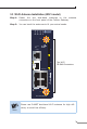
3.4 Wiring the Power Inputs The 6-contact terminal block connector on the top panel of Cellular Gateway is used for two redundant power inputs. Please follow the steps below to insert the power wire. Caution When performing any of the procedures like inserting the wires or tightening the wire-clamp screws, make sure the power is OFF to prevent from getting an electric shock. 1. Insert positive and negative DC power wires into contacts 1 and 2 for POWER 1, or 5 and 6 for POWER 2.
2. Tighten the wire-clamp screws for preventing the wires from loosening. 1 2 Power 1 + - Note Caution 3 4 Alarm 5 6 Power 2 + - The wire gauge for the terminal block should be in the range between 12 and 24 AWG. PWR1 and PWR2 must provide the same DC voltage while operating with dual power input. 3.5 Grounding the Device User MUST complete grounding wired with the device; otherwise, a sudden lightning could cause fatal damage to the device. EMD (Lightning) DAMAGE IS NOT CONVERED UNDER WARRANTY.
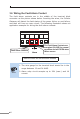
3.6 Wiring the Fault Alarm Contact The fault alarm contacts are in the middle of the terminal block connector as the picture shows below. Inserting the wires, the Cellular Gateway will detect the fault status of the power failure or port failure, and then will form an open circuit.
4. Starting Web Management The following shows how to start up the Web Management of the Cellular Gateway. Note the Cellular Gateway is configured through an Ethernet connection. Please make sure the manager PC must be set to the same IP subnet address. For example, the default IP address of the Cellular Gateway is 192.168.1.1, then the manager PC should be set to 192.168.1.x (where x is a number between 2 and 254), and the default subnet mask is 255.255.255.0.
4.1 Logging in to the Cellular Gateway 1. Use Web browser and enter IP address http://192.168.1.1 (the factory default IP address or the one that you have just changed in console) to access the Web interface. 2. When the following dialog box appears, please enter the default user name “admin” and password “admin” (or the password you have changed before) as shown in Figure 4-2. Default Default Default Default Default IP Address: 192.168.1.1 User Name: admin Password: admin SSID (2.4G): PLANET_2.
3. After entering the password, the main screen appears as shown in Figure 4-3. Figure 4-3: Web-based Main Screen of Cellular Gateway Now, you can use the Web management interface to continue the Cellular Gateway management or manage the Cellular Gateway by console interface. Please refer to the user’s manual for more. Administrators are strongly suggested to change the default password and Wi-Fi SSID on the first login to safeguard system security.
5. Recovering Back to Default Configuration IP address has been changed or admin password has been forgotten – To reset the IP address to the default IP address “192.168.1.1” or reset the login password to default value, press the hardware reset button on the front panel for about 15 seconds. After the device is rebooted, you can log in the management Web interface within the same subnet of 192.168.1.xx.
6. Customer Support You can browse our online FAQ resource and User’s Manual on PLANET Web site first to check if it could solve your issue. If you need more support information, please contact PLANET support team. PLANET online FAQs: https://www.planet.com.tw/en/support/faq Support team mail address: support@planet.com.tw ICG-2515 Series User’s Manual: https://www.planet.com.tw/en/support/downloads?&method=keyword& keyword=ICG-2515&view=3#list Copyright © PLANET Technology Corp. 2022.