
ICG-2510W-Series User Manual


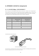

Table Of Contents
- 1. INTRODUCTION
- 2. INSTALLATION
- 3. CELLULAR GATEWAY MANAGEMENT
- 4. WEB CONFIGURATION
- 5. APPENDIX A RJ45 Pin Assignments

94
5. APPENDIX A RJ45 Pin Assignments
5.1. A.1 10/100/1000Mbps, 10/100/1000BASE-T
When connecting your 10/100/1000Mbps Cellular Gateway to another device, a bridge or a hub, a straight-through or
crossover cable is necessary. Each port of the Cellular Gateway supports auto-MDI/MDI-X detection. That means you
can directly connect the Cellular Gateway to any Ethernet devices without making a crossover cable. The following
table and diagram show the standard RJ45 receptacle/connector and their pin assignments:
RJ45 Connector pin assignment
Contact MDI
Media Dependent
Interface
MDI-X
Media Dependent
Interface-Cross
1 Tx + (transmit) Rx + (receive)
2 Tx - (transmit) Rx - (receive)
3 Rx + (receive) Tx + (transmit)
4, 5 Not used
6 Rx - (receive) Tx - (transmit)
7, 8 Not used
The standard cable, RJ45 pin assignment
The standard RJ45 receptacle/connector
There are 8 wires on a standard UTP/STP cable and each wire is color-coded. The following shows the pin allocation
and color of straight-through cable and crossover cable connection: