
ICG-2510W-Series User Manual
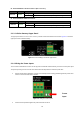
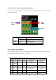
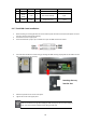
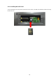
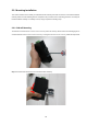
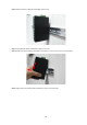
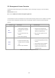
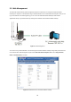
Table Of Contents
- 1. INTRODUCTION
- 2. INSTALLATION
- 3. CELLULAR GATEWAY MANAGEMENT
- 4. WEB CONFIGURATION
- 5. APPENDIX A RJ45 Pin Assignments

22
2.1.5. Wiring the Digital Input/Output and Relay
The two 3-contact terminal block connectors on the top panel of ICG-2510W(G)-LTE Series is used for Digital Input,
Digital Output and Relay.
Figure 2-6 Wiring the DI/DO Inputs and Relay
DI
Input ON 5 to 30 VDC
Input OFF 0 to 3 VDC
DO Output < 50mA @ 30VDC
RELAY Load capability 1A 250VAC/30VDC
2.1.6. Console Line Definition
Insert the RJ45 end of the console cable into the RJ45 outlet with sign “console”, and insert the DB9F end of the
console cable into the RS232 serial interface of user’s device.
The signal connection of the console cable is as follows:
Console line definition (RS232)
RJ45 Color Signal DB9F Description Dir (Router)
1
White/
Orange
A 8 RS485-A Input/Output
2 Orange B 6 RS485-B Input/Output
3
White/
Green
RXD 2 Receive Data Output
4 Blue DCD 1 Data Carrier Detect Output
5 White/ GND 5 System Ground
Digita
l Input
Digital
Output
Relay