
ICG-2510W-Series User Manual
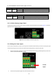
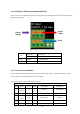
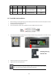
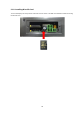
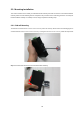
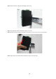
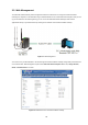
Table Of Contents
- 1. INTRODUCTION
- 2. INSTALLATION
- 3. CELLULAR GATEWAY MANAGEMENT
- 4. WEB CONFIGURATION
- 5. APPENDIX A RJ45 Pin Assignments

21
10/100/1000BASE-T LAN Port Interfaces (Port-1 to Port-4)
LED
Color
Function
Ethernet Green
Lights
Indicates that the link is successfully established.
Blinking
Indicates that the port is actively sending or receiving data.
10/100/1000BASE-T WAN Port Interface
LED
Color
Function
Ethernet Green
Lights
Indicates that the link is successfully established.
Blinking
Indicates that the port is actively sending or receiving data.
2.1.3. Cellular Gateway Upper Panel
The upper panel of the Industrial Cellular Gateway consists of three terminal block connectors. Figure 2-4 shows the
upper panel of the Cellular Gateway.
Figure 2-4: ICG-2510W(G)-LTE Series Upper Panel
2.1.4. Wiring the Power Inputs
The 2-contact terminal block connector on the top panel of Industrial Cellular Gateway is used for one DC power input.
The power input range is from 9 to 36V DC. Please follow the steps below to insert the power wire.
1. Please read the above description of upper panel carefully before inserting positive/negative DC power wires
into the 2-contact terminal block connector.
Figure 2-5: Wiring the Power Inputs
2. Confirm that the positive/negative DC power wires will not fall off.
Power
Input