
User's Manual
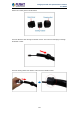
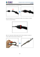

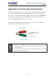

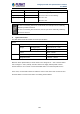

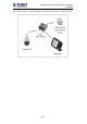
Table Of Contents
- Chapter 1. Product Introduction
- Chapter 2. Hardware Interface
- 2.1 Physical Descriptions
- 2.2 Hardware Installation
- 2.3 Initial Utility Installation
- 2.4 Using UPnP of Windows XP or 7
- 2.5 Setting Up ActiveX for the Camera
- Chapter 3. Web-based Management
- Appendix A. The Dimensional Diagram of the Stand
- Appendix B. The Dimensional Diagram of the Camera
- Appendix C. Ping IP Address
- Appendix D. Configuring Port Forwarding Manually
- Appendix E. Waterproofing the Cable Connections
- Appendix F. Joystick Compatibility
- Appendix G. Connecting Audio Devices
- Appendix H. Connecting Digital Input/ Digital Output Devices
- Appendix I. How to Replace the Fuse
- Appendix J. Troubleshooting & Frequently Asked Questions

2 Mega-pixel PoE Plus Speed Dome IP Camera
ICA-E6260
149
Consequently, to connect a second DI or DO device, use the GND and DI1 cables to connect
the second DI device, and the 12V and DO2 cables for the second DO device.
High Voltage DO Device Connection
Even though the camera provides 12V power, this may not be enough for some high voltage
DO devices, such as a ceiling light or a motor that opens or closes a gate. In this case, there
is a need to connect an external relay. See wiring scheme below:
Note that when choosing an appropriate relay, please refer to its specifications and make
sure they match the above design. The triggering circuit voltage has to be around 12V DC
and the switch-controlled circuit voltage has to match the external power supply (e.g. 110V
AC or 220V AC).