
User's Manual
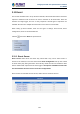
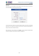
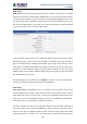
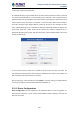
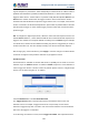
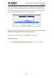
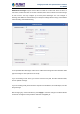
Table Of Contents
- Chapter 1. Product Introduction
- Chapter 2. Hardware Interface
- 2.1 Physical Descriptions
- 2.2 Hardware Installation
- 2.3 Initial Utility Installation
- 2.4 Using UPnP of Windows XP or 7
- 2.5 Setting Up ActiveX for the Camera
- Chapter 3. Web-based Management
- Appendix A. The Dimensional Diagram of the Stand
- Appendix B. The Dimensional Diagram of the Camera
- Appendix C. Ping IP Address
- Appendix D. Configuring Port Forwarding Manually
- Appendix E. Waterproofing the Cable Connections
- Appendix F. Joystick Compatibility
- Appendix G. Connecting Audio Devices
- Appendix H. Connecting Digital Input/ Digital Output Devices
- Appendix I. How to Replace the Fuse
- Appendix J. Troubleshooting & Frequently Asked Questions

2 Mega-pixel PoE Plus Speed Dome IP Camera
ICA-E6260
107
The configurable responses are classified as Digital I/O ports, Notification messages, Upload
Video/Snapshot and Audio and Send URL Commands.
Digital I/O ports appear only for the camera models that support this function.
Digital I/O ports
Digital input/output ports (select models only) are used to connect digital input (DI) and digital
output (DO) devices. DI is a trigger device like a switch or sensor (e.g., “panic button”), which
when pressed or triggered, notifies the camera to perform specific actions or the DO device
to respond. DO’s can be alarms or lights, etc.
The Digital I/O Ports page displays the number of available DI and DO ports on the camera,
which varies depending on camera model.
DI: To configure the digital input device, define the active level and trigger interval of the DI.
The default Active Level is “0”, which means the DI device remains inactive unless triggered.