User's Manual GSW-1602SF GSW-2404SF GSW-2416SF 10/100/1000Mbps 16/24-Port Web Smart Gigabit Ethernet Switch
Trademarks Copyright © PLANET Technology Corp. 2008. Contents subject to which revision without prior notice. PLANET is a registered trademark of PLANET Technology Corp. All other trademarks belong to their respective owners.
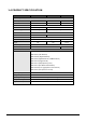
TABLE OF CONTENTS 1. INTRODUCTION............................................................................................................................................................. 1 1.1 PACKAGE CONTENTS .................................................................................................................................................... 1 1.2 HOW TO USE THIS MANUAL ........................................................................................................................
.9.1 IGMP Snooping Configuration........................................................................................................................... 45 4.9.2 IGMP Snooping Status...................................................................................................................................... 46 4.9.3 Multicast Group Table ....................................................................................................................................... 48 4.
1. INTRODUCTION 1.1 Package Contents Check the contents of your package for following parts: ● Web Smart Gigabit Ethernet Switch x1 ● CD-ROM user's manual x1 ● Quick installation guide x1 ● 19” rack mounting kit x1 ● Power cord x1 ● Rubber feet x 4 If any of these are missing or damaged, please contact your dealer immediately, if possible, retain the carton including the original packing material, and use them against to repack the product in case there is a need to return it to us for repair.
GSW-1602SF - shared with Port-15 and Port-16. GSW-2404SF - shared with Port-21 to Port 24. GSW-2416SF - shared with Port-1 to Port-8, Port-17 to Port-24 z Each Switching ports support auto-negotiation-10/20Mbps, 100/200Mbps and 1000/2000Mbps supported z Auto-MDI/MDI-X detection on each RJ-45 port, support CSMA/CD protocol z Prevents packet loss with back pressure (Half-Duplex) and IEEE 802.
1.4 PRODUCT SPECIFICATION Model GSW-1602SF GSW-2404SF GSW-2416SF Network ports 16 24 24 SFP/mini-GBIC slot 2 4 16 Hardware Specification Switch architecture Store-and-Forward Switch Fabric Switch throughput 32Gbps 48Gbps 23.8Mpps 35.7Mpps Address Table 8K entries Share data Buffer Flow Control 340KB 500KB Back pressure for half duplex, IEEE 802.3x Pause Frame for full duplex Dimensions (mm) 440 x 210 x 44 (1U height) Weight 2kg 2kg Power Requirement 2.
2. INSTALLATION This section describes the functionalities of GSW-1602SF/GSW-2404SF/GSW-2416SF’s components and guides how to install it on the desktop or shelf. Basic knowledge of networking is assumed. Please read this chapter completely before continuing. 2.1 Product Description The PLANET GSW-1602SF/GSW-2404SF/GSW-2416SF is a 16/24-Port 10/100/1000Mbps Web Smart Gigabit Ethernet Switch with non-blocking wire-speed performance.
2.1.3 LED Indicators LED of GSW-1602SF / GSW-2404SF ■ LED Color PWR Green 1000 LNK/ACT 10/100 LNK/ACT SFP LNK/ACT Green Green Green Function Lights to indicate that the Switch is powered on. Lights to indicate that the Switch is successfully connecting to the network at 1000Mbps. Blinks to indicate the Switch is receiving or sending data. Lights to indicate that the Switch is successfully connecting to the network at 10/100Mbps. Blinks to indicate the Switch is receiving or sending data.
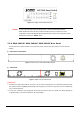
Figure 2-5 PLANET GSW-2416SF LED panel #Note: To press 5 seconds and release the RESET button. The GSW-1602SF/GSW-2404SF /GSW-2416SF will back to the factory default mode. Be sure that you backup the current configuration of GSW-1602SF/GSW-2404SF/GSW-2416SF; else the entire configuration will be erased when pressing the “RESET” button. 2.1.4 GSW-1602SF/GSW-2404SF/GSW-2416SF Rear Panel The rear panel of the Switch indicates an AC inlet power socket, which accepts input power from 100 to 240V AC, 50-60Hz.
2.2 Install the GSW-1602SF/2404SF/2416SF This section describes how to install your GSW-1602SF/GSW-2404SF/GSW-2416SF Web Smart Gigabit Ethernet Switch and make connections to the Switch. Please read the following topics and perform the procedures in the order being presented. PLANET GSW-1602SF/GSW-2404SF/GSW-2416SF Web Smart Gigabit Ethernet Switch do not need software configuration. To install your GSW-1602SF/GSW-2404SF/GSW-2416SF on a desktop or shelf, simply complete the following steps. 2.2.
Caution: You must use the screws supplied with the mounting brackets. Damage caused to the parts by using incorrect screws would invalidate your warranty. Step3: Secure the brackets tightly. Step4: Follow the same steps to attach the second bracket to the opposite side.
Approved PLANET SFP Transceivers PLANET GSW-1602SF/GSW-2404SF/GSW-2416SF support both single mode and multi mode SFP transceiver. The following list of approved PLANET SFP transceivers is correct at the time of publication: ■MGB-SX SFP (1000BASE-SX SFP transceiver ) ■MGB-LX SFP (1000BASE-LX SFP transceiver ) #Note: It recommends using PLANET SFPs on the Switch. If you insert a SFP transceiver that is not supported, the Switch will not recognize it.
3. SWITCH MANAGEMENT This chapter describes how to manage the GSW-1602SF/GSW-2404SF/GSW-2416SF. Topics include: - Overview - Management methods - Assigning an IP address to the GSW-1602SF/GSW-2404SF/GSW-2416SF - Logging on to the GSW-1602SF/GSW-2404SF/GSW-2416SF 3.1 Overview This chapter gives an overview of switch management. The GSW-1602SF/GSW-2404SF/GSW-2416SF provides a simply Web browser interface.
Using this management method: The GSW-1602SF/GSW-2404SF/GSW-2416SF must have an Internet Protocol (IP) address accessible for the remote host. The screen in Figure 3-1 appears. Figure 3-1 Web Management via ethernet 3.2.2 Login the Switch Before you start configure the GSW-1602SF/GSW-2404SF/GSW-2416SF, please note the GSW-1602SF/GSW-2404SF/GSW-2416SF is configured through an Ethernet connection, make sure the manager PC must be set on same the IP subnet address.
4. CONFIGURATION The GSW-1602SF/GSW-2404SF/GSW-2416SF Web Smart Gigabit Ethernet Switch provide Web interface for Switch smart function configuration and make the Switch operate more effectively - They can be configured through the Web Browser. A network administrator can manage and monitor the GSW-1602SF /GSW-2404SF/GSW-2416SF from the local LAN. This section indicates how to configure the Switch to enable its smart function.
◆ MAC Address – Dynamic Address Table / Static MAC Address. Explain in section 4.13 ◆ Tools – Reboot / Factory Reset / Firmware Update / Configuration Upload / Ping / Cable Diagnostic. Explain in section 4.14 ◆ Status – Port Statistics Overview / Port Statistics Detail / LACP Status / RSTP Status / IGMP Snooping Status / Multicast Group Status. Explain in section 4.15 4.2 System 4.2.1 System Info The System Info page provides information for the current device information.
4.2.2 Misc Configuration The Misc Configuration includes the DHCP Enabled, IP Subnet address, Power Saving and Management VLAN. System name and description, password, Inactivity Timeout and SNMP enable and SNMP related function. The screen in Figure 4-3 appears. Figure 4-3 Misc Configuration screen The page includes the following configurable data; see the table 4-2 description of the Misc Configuration.
System Description Defines the user-defined device description Password - This function provides administrator to secure Web login Inactivity Timeout – Specifies a time period for the user login. The web interface will be auto logout if there’re no actions from the login user. The default value is 300 seconds; 0 means no inactivity time limit. SNMP Enable – Enable or Disable the SNMP function of the device.
4.3 Port Configuration This function allows displaying each port’s status. The Link Status in the screen displays the current connection speed and duplex mode; else this function will show down when the port is disconnected. Press the “Refresh” button to renew the screen. The screen in Figure 4-4 appears. Figure 4-4 Port Configuration screen The page includes the following configurable data; see the table 4-3 description of the Port Configuration.
Backpressure is enabled on Half-Duplex mode. • Disable – No flow control or backpressure function on no matter Full-Duplex or Half-Duplex mode • Ingress Rate Limit The value of inbound traffic limitation in kilobit-per-second (kbps). Per port in step of 128 kbps. Default : No Limit The range between 128 Kbps to 3968 kbps. • Egress Shaping The value of outbound traffic limitation in kilobit-per-second (kbps). Per port in step of 128 kbps. Default : No Limit The range between 128 Kbps to 3968 kbps.
4.4 Port Mirroring This function provide to monitoring network traffic that forwards a copy of each incoming or outgoing packet from one port of a network Switch to another port where the packet can be studied. It enables the manager to keep close track of switch performance and alter it if necessary. The Port Mirroring screen in Figure 4-5 appears. Figure 4-5 Mirror Setting screen The page includes the following configurable data table 4-4 description of the Port Mirroring.
4.5 Storm Control This function provide various type of storm control of the device, such as ICMP Rate , Learn Frames Rate, Broadcast Rate, Multicast Rate and Flooded unicast Rate. The Storm Control screen in Figure 4-6 appears. Figure 4-6 Storm Control screen The page includes the following configurable data table 4-5 description of the Storm Control.
4.6 VLANs A Virtual LAN (VLAN) is a logical network grouping that limits the broadcast domain. It allows you to isolate network traffic so only members of the VLAN receive traffic from the same VLAN members. Basically, creating a VLAN from a switch is logically equivalent of reconnecting a group of network devices to another Layer 2 switch. However, all the network devices are still plug into the same switch physically. The GSW-1602SF/GSW-2404SF/GSW-2416SF switch supports IEEE 802.
4.6.1 VLAN Membership This function group individual ports into a small “Virtual” network of their own to be independent of the other ports. The screen in Figure 4-7 appears. Figure 4-7 VLAN Membership screen The page includes the following items: table 4-6 description of the Add a VLAN. • Item Description • VLAN ID - Specify the VLAN Identifier for the new VLAN. (You can only enter data in this field when you are creating a new VLAN.) The range of the VLAN ID is (1 to 4094).
As show in Figure 4-8 and Figure 4-9 Figure 4-8 Add a VLAN screen Figure 4-9 VLAN Member Setup screen 4.6.1.2 Modify the VLAN Group Member Once you want to modify the existence VLAN Group member or delete a existence VLAN Group. Refer to the following steps. 1. To modify the members of an existence VLAN Group, check the VLAN Group ID and press “Modify” button. the ID VLAN Setup screen will pop out. 2.
Figure 4-10 VLAN Group – member modify and delete VLAN Group screen #Note: Once the VLAN Group be deleted, the Ports with the PVID set to this VLAN Group have to re-configure the PVID. Or the PVID will be set to “None” 4.6.2 Per Port Configuration The VLAN Per Port Configuration page contains fields for managing ports that are part of a VLAN. The port default VLAN ID (PVID) is configured on the VLAN Port Configuration page. All untagged packets arriving to the device are tagged by the ports PVID.
• Item Description • VLAN Type - There’re two VLAN mode support – 802.1Q VLAN and Port-Bas VLAN • 802.1Q – Packets income will be tagged with VID as the PVID setting. All ports on the switch belong to default VLAN (VID 1). • Port-Base - Packets can only be broadcast among other members of the same VLAN group. Note all unselected ports are treated as belonging to the default system VLAN. If port-based VLAN are enabled, then VLAN-tagging feature is ignored.
4.6.3 VLAN setting example: 4.6.3.1 Two separate 802.1Q VLAN The diagram shows how the switch handle Tagged and Untagged traffic flow for two VLANs. VLAN Group 2 and VLAN Group 3 are separated VLAN. Each VLAN isolate network traffic so only members of the VLAN receive traffic from the same VLAN members. The screen in Figure 4-12 appears and Table 4-8 describes the port configuration of switch.
Untagged packet entering VLAN 3 1. While [PC-4] transmit an untagged packet enters Port-4, the switch will tag it with a VLAN Tag=3. [PC-5] and [PC-6] will received the packet through Port-5 and Port-6. 2. While the packet leaves Port-5, it will be stripped away it tag becoming an untagged packet. 3. While the packet leaves Port-6, it will keep as a tagged packet with VLAN Tag=3.
Figure 4-14 Assign VLAN members for VLAN 2 and VLAN 3 Remember to remove the Port 1 – Port 6 from VLAN 1 membership, since the Port 1 – Port 6 had be assigned to VLAN 2 and VLAN 3. Figure 4-15 Remove specify ports from VLAN 1 member #Note: It’s import to remove the VLAN members from VLAN 1 configuration. Or the ports would become overlap setting.
3. Assign PVID for each port: Port-1,Port-2 and Port-3 : PVID=2 Port-4,Port-5 and Port-6 : PVID=3 Port-7~Port-24 : PVID=1 4. Enable VLAN Tag for specific ports Link Type : Port-3 (VLAN-2) and Port-6 (VLAN-3) The Per Port VLAN configuration in Figure 4-16 appears. Figure 4-16 Port 1-Port 6 VLAN Configuration 4.6.3.2 Two VLANs with overlap area Follow the example of 4.6.3.1.
1. Specify Port-7 on the device to connect to the server. 2. Assign Port-7 to both VLAN 2 and VLAN 3 at the VLAN Member configuration page. The screen in Figure 4-18 appears. Figure 4-18 VLAN overlap port setting 3. Define a VLAN 1 as a “Public Area” that overlapping with both VLAN 2 members and VLAN 3 members.
4. Setup Port-7 with “PVID=1” at VLAN Per Port Configuration page. The screen in Figure 4-20 appears. Figure 4-20 Setup Port-7 with PVID-1 That is, although the VLAN 2 members: Port-1 to Port-3 and VLAN 3 members: Port-4 to Port-6 also belongs to VLAN 1. But with different PVID settings, packets form VLAN 2 or VLAN 3 is not able to access to the other VLAN. 4.6.3.3 VLAN Trunking between two 802.1Q aware switch The most cases are used for “Uplink” to other switches.
About the VLAN ports connect to the hosts, please refer to 4.5.3.1 and 4.5.3.2 examples. The following steps will focus on the VLAN Trunk port configuration. 1. Specify Port-8 to be the 802.1Q VLAN Trunk port, and the Trunking port must be a Tagged port while egress. The Port-8 configuration as the following screen in Figure 4-22. Figure 4-22 The configuration of VLAN Trunk port 2. Assign the VLAN Trunk Port to be the member of each VLAN – which wants to be aggregated.
4.7 Rapid Spanning Tree Spanning Tree Protocol (STP) provides tree topography for any arrangement of bridges. STP also provides one path between end stations on a network, eliminating loops. Rapid Spanning Tree Protocol (RSTP) - While Classic Spanning Tree guarantees preventing L2 forwarding loops in a general network topology, convergence can take up to 30-60 seconds. The convergence time is considered too long for many applications. When network topology allows, faster convergence may be possible.
4.7.1 RSTP System Configuration The “RSTP System Configuration” table allows configuring the spanning tree parameters. Figure 4-25 RSTP System Configuration The page includes the following fields: table 4-9 description of the RSTP System Configuration. • Item Description • RSTP Enabled Enabled –Enabled the RSTP. Disabled -Disable the RSTP. • System Priority - Specifies the bridge priority value. When switches or bridges are running STP, each is assigned a priority.
provide faster spanning tree convergence, without creating forwarding loops. Compatible – Classis STP (802.1d): Provides a single path between end stations, avoiding and eliminating loops. • Loop detection Enable or disable the loop detection. Table 4-9 Description of the RSTP System Configuration #Note: • Max Age -. The value lies between 6 and 40, with the value being less than or equal to "(2 * Bridge Forward Delay) - 1" and greater than or equal to "2 * (Bridge Hello Time +1)".
• Path Cost The port contribution to the root path cost. The path cost is adjusted to a higher or lower value, and is used to forward traffic when a path being rerouted. Value Rage : 1-20000000 Default Path Cost -- The default path cost of the port is automatically set by the port speed and the default path cost method. The default values for path costs are: - Ethernet - 2000000 - Fast Ethernet - 200000 - Gigabit Ethernet - 20000 • Port Priority The value of the port priority. The default value is “128”.
RSTP VLAN Bridge Overview The information of the RSTP Root shows in the Bridge overview table. The screen in Figure 4-28 appears. Figure 4-28 RSTP Status screen The page includes the following fields: table 4-11 description of the RSTP VLAN Bridge Overview. • Item Description • VLAN Id Identifies VLANs associated with the Rapid Spanning Tree. • Bridge IDd Identifies the Bridge priority and MAC address. • Hello Time Minimum time between transmissions of Configuration BPDUs.
RSTP Port Status The information of the RSTP per Port and Trunk group shows in the RSTP Port Status table. The screen in Figure 4-29 appears. Figure 4-29 RSTP Status screen The page includes the following fields: table 4-12 description of the RSTP Port status. • Item Description • Port/Group Port or Link Aggregation group on which Rapid STP is enabled • VLAN Id Port or Link Aggregation interfaces associated with VLANs associated with the Rapid Spanning Tree.
#Note: A port transitions from one state to another as follows: • From initialization (switch boot) to blocking • From blocking to listening or to disabled • From listening to learning or to disabled • From learning to forwarding or to disabled • From forwarding to disabled • From disabled to blocking -38-
4.8 Link Aggregation Port Aggregation optimizes port usage by linking a group of ports together to form a single Link Aggregated Groups (LAGs). Port Aggregation multiplies the bandwidth between the devices, increases port flexibility, and provides link redundancy. Each LAG is composed of ports of the same speed, set to full-duplex operations. Ports in a LAG, can be of different media types (UTP/Fiber, or different fiber types), provided they operate at the same speed.
• Item Description • Port Indicate port 1 to port 24. • Normal While a port is checked as “Normal”, the port is not joining to any Static Trunk Group. • Group Specify the Joined Trunk Group. There’re maximum eight trunk groups per system. With different switch model, the maximum number of ports are as follow: GSW-1602SF – Up to 8 ports per Trunk Group GSW-2404SF – Up to 12 ports per Trunk Group A port can be assigned to only one Trunk Group.
• Item Description • Port Indicate port 1 to port 24. • Protocol Enable To Enable or disable the LCAP protocol on a selected port. Once the LACP protocol be enabled, the system will start transmit the LACP control packets and exchange with another LACP aware switch. If the linked switch didn’t support LACP, then the aggregated link will not be established. • Key Value The Key Value will be filed in the LACP control packets. Ports with same key value will be set to the same LACP Group.
4.8.3 LACP Status The LACP Status page display the current LACP aggregation Groups and LACP Port status. To open LACP Status screen perform the folling: 1. Click Status -> LACP Status 2. The “LACP Aggregation Overview” and “LACP Port Status” screen is displayed as in Figure 4-32. Figure 4-32 LACP Status LACP Aggregation Overview Table The LACP Aggregation Overview Table lists the active LACP ports and mapped Group. It also indicates the Partner Port number of the other LACP aware switches.
The page includes the following fields: table 4-15 description of the LACP Aggregation Overview. • Item • Group / Port • Normal Description Indicate port 1 to port 24. While a port is checked as “Normal”, the port is not joining to any LACP Trunk Group. The Linked LACP aggregation group. The Group ID is the fist port ID of the LACP group member. ex.
The page includes the following fields: table 4-16 description of the LACP Port Status. • Item Description • Port Indicate port 1 to port 24. • Protocol Active Indicate the LCAP protocol is enable or not on the port. Yes- LACP is enabled and active on the port No- LACP is not enabled, or LACP is enabled but not active on the port. It’s usually depends on the partner switch is LACP enabled or not. • Partner Port Number The port number/ID of the linked partner switch- if other switch has LACP enabled.
4.9 IGMP Snooping The Internet Group Management Protocol (IGMP) lets host and routers share information about multicast groups memberships. IGMP snooping is a switch feature that monitors the exchange of IGMP messages and copies them to the CPU for feature processing. The overall purpose of IGMP Snooping is to limit the forwarding of multicast frames to only ports that are a member of the multicast group. 4.9.
configuration. Add a new VLAN group and the Table will add the VLAN entry automatically. • IGMP Snooping Enabled Enables or disables IGMP snooping on the VLAN. Ports be assign to the VLAN will be applied to filter the Multicast stream. Enabled is the default value. • IGMP Querying Enabled Enables or disables IGMP Query mode on the VLAN. The Query mode is used to periodically check the multicast group for members that are no longer active.
The page includes the following fields: table 4-18 description of the IGMP Snooping Status. • Item Description • VLAN ID Identifies a VLAN and contains information about the Multicast group configuration. • Querier Display the current status of IGMP Querier on the device. Active – The IGMP Query function had been enabled on the device and played as a main Querier within a subnet domain. Within a network domain, there will be only one IGMP Querier.
4.9.3 Multicast Group Table The Multicast Group page displays the ports attached to the Multicast service group in the Ports tables. The Port a tables also reflect the manner in which the port joined the Multicast group. Ports can be added either to existing groups or to new Multicast service groups. The Bridge Multicast Group page permits new Multicast service groups to be created. The Bridge Multicast Group page also assigns ports to a specific Multicast service address group.
4.10 Quality of Service Quality of Service (QoS) is an advanced traffic prioritization feature that allows you to establish control over network traffic. QoS enables you to assign various grades of network service to different types of traffic, such as multi-media, video, protocol-specific, time critical, and file-backup traffic. QoS reduces bandwidth limitations, delay, loss, and jitter.
The QoS Configuration page in Figure 4-38 appears. Figure 4-38 QoS Configuration screen 4.10.1 802.1p QoS Mode QoS settings allow customization of packet priority in order to facilitate delivery of data traffic that might be affected by latency problems. The IEEE 802.1p Priority specification uses 8 priority levels to classify data packets. The screen in Figure 4-39 and Figure 4-40 appears. Figure 4-39 802.
Figure 4-40 Prioritize Traffic screen The page includes the following fields: Table 4-20 Description of the QoS Configuration. • Item Description • Prioritize Traffic The draw menu allows customization of 802.1p to Traffic classifiers. Total 5 selections for the Prioritize Traffic. • Custom – Manual mapping the 802.1p priority to the 4-level queues. Setup at the next table. • All Low Priority - mapping all 802.1p tagged packets to Queue 0 • All Normal Priority - mapping all 802.
4.10.2 DSCP QoS Mode DiffServ Code Point (DSCP) - is the traffic prioritization bits within an IP header that are encoded by certain applications and/or devices to indicate the level of service required by the packet across a network. The DSCP Configuration page provides fields for defining output queue to specific DSCP fields. Select the QoS mode to DSCP, the DSCP to queue mapping configuration page appears, as the Figure 4-41 shows.
4.11 802.1X Management The PALENT GSW-1602SF/GSW-2404SF/GSW-2416SF supports IEEE 802.1X Port-base network access control and RADIUS server authentication to enhance the host link more security. An 802.1X Infrastructure is composed of three major components: Authenticator, Authentication server, and Supplicant. Authentication server – (RADIUS Server): An entity that provides an authentication service to an authenticator.
9. The RADIUS server sends Web-Smart Switch a RADIUS ACCEPT message. 10. Web-Smart Switch sends the client an EAP Success message along with the broadcast key and key length. This section is to control the access of the switch, includes the user access and management control. The 802.1X Management page contains links to the following topics: • RADIUS Server Configuration • Port Access Control 4.11.1 RADIUS Server Configuration This page is to configure the RADIUS server connection features.
The RADIUS Server configuration table includes the following fields: Table 4-22 Description of the 802.1X Configuration. • Item Description • Mode To Enable/Disable the port access control administrative mode This selector lists the two options for administrative mode: enable and disable. The default value is disabled.. • RADIUS Server IP The IP address of the RADIUS server being added. • RADIUS UDP Port The UDP port used by this server. The valid range is 0 - 65535. The default UDP Port No.
4.11.2 Port Access Control This table is to configure the per port network access control setting. By drawing and select the menu bar to define the port control type. The screen in Figure 4-45 and Figure 4-46 appears. Figure 4-45 Per Port network access control configure table Figure 4-46 802.1X Network access control mode selection The Network Access Control port configuration table includes the following fields: Table 4-23 Description of the Port Access Control.
it will be grayed out. Once this button is pressed, the action is immediate. It is not required to press the Submit button for the action to occur. • Force Reinitialize This button begins the re-initialization sequence on the selected port. This button is only selectable if the control mode is 'auto'. If the button is not selectable, it will be grayed out. Once this button is pressed, the action is immediate. It is not required to press the Submit button for the action to occur.
4.12 Filter Configuration The GSW-1602SF/GSW2404SF/GSW-2416SF support per-Port IP Filter function to management the IP traffic flow. With the IP Filter configuration, administrator can block the specify source IP Address range. The screen in Figure 4-48 appears. Figure 4-48 Filter Configuration screen The Filter Configuration page includes the following fields: Table 4-25 Description of the Filter Configuration. • Item Description • Port Indicate port 1 to port 24 for the IP Filter setting.
4.13 MAC Addresses 4.13.1 Dynamic Address Table Use this page to set the Address Ageing Timeout for the MAC Address database, and to display information about entries in the MAC Address database. These entries are used by the transparent bridging function to determine how to forward a received frame. The screen in Figure 4-49 appears.
• MAC-Address Specifies the MAC address for which the table is queried. Table 4-26 Description of the Dynamic Address Table "Note: Although the MAC Address Table of GSW-Series Web-Smart switches are up to 8K .entries. To reduce the Web-Page memory loading, the maximum MAC lists are limited to 256 entries. 4.13.2 Static MAC Address The Static MAC Address page contains a list of static MAC addresses. Static Address can be added and removed from the page.
The MAC Address Table includes the following fields: Table 4-28 Description of the Static MAC Address. • Item Description • VID The VLAN ID attached to the MAC Address • Ports Specifies the port numbers for which the table is queried. • Type Static - Static addresses are manually configured. Packets received with the destinated MAC address mathch the port static MAC setting will be forward to the specify port. • MAC-Address The MAC address listed in the current static address list.
Hardware Reset button 4.14.3 Firmware Upgrade The Firmware Upgrade page contains fields for downloading system image files from the Local File browser to the device. To open Firmware Upgrade screen perform the folling: 1. Click Tools -> Firmware Upgrade 2. The Firmware Upgrade screen is displayed as in Figure 4-53. 3. Click the “Browse” button of the main page, the system would pop up the file selection menu to choose firmware. 4.
"Note: Does not power off the Switch until the update progress is complete? "Note: Do not quit the Firmware Upgrade page without press the “Yes” button - after the image is loaded. Or the system won’t apply the new firmware. The user have to repeat the firmware upgrade processes again.
4.14.4 Configuration Upload This function allows backup and reload the current configuration of GSW-1602SF /2404SF/GSW-2416SF to the local management station. The screen in Figure 4-55 appears. Configuration Upload: Upload the existed configuration file to the GSW-1602SF/GSW-2404SF/GSW-2416SF. The configuration file had been saved at the local machine already. Configuration Download: Download the current configuration file of the switch to the local machine.
2. Select on the configuration file then click “Upload”, the bottom of the browser shows the upload status. 3. After down, the main screen appears “Transfer Completed”. Configuration Download 1. Press the “Download” button to save the current configuration in manager workstation. The following screens in Figure 4-57 and 4-58 appears. Figure 4-57 File Download screen 2. Chose the file save path in management workstation.
4.14.5 Ping Use this screen to tell the switch to send a Ping request to a specified IP address. You can use this to check whether the switch can communicate with a particular IP station. Once you click the Apply button, the switch will send n pings and the results will be displayed below the configurable data. Figure 4-59 Ping function screen The Ping Parameters includes the following fields: Table 4-29 Description of the Ping Parameters.
"Note: Be sure the target IP Address is within the same network subnet of the switch, or you had setup the correct gateway IP address. 4.14.6 Cable Diagnostics The Cable Diagnostics page contains fields for performing tests on copper cables. These functions have the ability to identify the cable length and operating conditions, and to isolate a variety of common faults that can occur on the Cat5 twisted-pair cabling.
Table 4-30 Description of the Cable Diagnostics The Cable status includes the following items: Table 4-31 Description of the Cable Status. • Item Description • Pair The twist pair of the UTP cable. The pair groups as follow: A (Pin 1,2) B (Pin 3,6) C (Pin 4,5) D (Pin 7,8) • Length[m] When properly terminated, Cable Diagnostics reports the approximate cable length in meters of each of the four cable pair A, B, C, and D. • Status The cable test results.
4.14.7 Web Smart Function This function could provide you to define device indicate connect to each port on Web Smart Switch, the screen in Figure 4-62 appears. Figure 4-62 Web Smart Function Web Page screen The available options are shown as below: Table 4-32 Description of the Web smart function.
• Other Table 4-32 Description of the Web smart function Assign an icon to specific port 1. Choose a device icon from options of Select a port function. 2. Check the port that need to marked. 3. After setup completed, press “Save” to save current configuration. 4. Please press “Back” for return to Web Smart Function screen. Assign an icon to all ports 1. Choose a device icon from options of Select a port function. 2. Check the box “Apply to all ports”. 3.
4.15 Status Click on the “Status” to present the Switch status on this screen, it displays the following status: Port Statistics LACP Status RSTP Status IGMP Snooping Status Multicast Group Table 4.14.1 Port Statistics The Port Statistic page displays the status of packet count from each port. The Port statistics screen in Figure 4-64 appears. Figure 4-64 Port Statistics screen The page includes the following fields: Table 4-33 Description of the Port Statistics.
• Receive Multicast Number of Multicast packets received on the selected port. • Receive Broad and Multicast Subtotal number of Broadcast and Multicast packets received on the selected port. • Receive Errors Packets The number of error packets received on the selected port. • Transmit Packets Number of total packets transmitted from the selected port. Include the Unicast , broadcast and multicast packets.
Logout Press this function; the web interface will go back to login screen. The screen in Figure 4-65 & 4-66 appears.
5. SWITCH OPERATION 5.1 Address Table The Switch is implemented with an address table. This address table composed of many entries. Each entry is used to store the address information of some node in network, including MAC address, port no, etc. This information comes from the learning process of Ethernet Switch. 5.2 Learning When one packet comes in from any port, the Switch will record the source address, port no. And the other related information in address table.
5.6 IGMP Snooping Theory Computers and network devices that want to receive multicast transmissions need to inform nearby routers that they will become members of a multicast group. The Internet Group Management Protocol (IGMP) is used to communicate this information. IGMP is also used to periodically check the multicast group for members that are no longer active. In the case where there is more than one multicast router on a sub network, one router is elected as the ‘queried’.
The states a computer will go through to join or to leave a multicast group are shown below: Non-Member Leave Group (Stop Timer) Delaying Member Join Group (Send Report, Start Timer) Query Received (Start Timer) Report Received (Stop Timer) Timer Expried (Send report) IGMP State Transitions -76- Leave Group Idle Member
6. TROUBLESHOOTING This chapter contains information to help you solve problems. If the Switch is not functioning properly, make sure the Ethernet Switch was set up according to instructions in this manual. The Link LED is not lit Solution: Check the cable connection and remove duplex mode of the Switch. Some stations cannot talk to other stations located on the other port Solution: Please check the VLAN, port trunking function that may introduce this kind of problem.
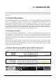
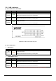
APPENDIX A A.1 Switch‘s RJ-45 Pin Assignments 1000Mbps, 1000Base T Contact MDI MDI-X 1 BI_DA+ BI_DB+ 2 BI_DA- BI_DB- 3 BI_DB+ BI_DA+ 4 BI_DC+ BI_DD+ 5 BI_DC- BI_DD- 6 BI_DB- BI_DA- 7 BI_DD+ BI_DC+ 8 BI_DD- BI_DC- Implicit implementation of the crossover function within a twisted-pair cable, or at a wiring panel, while not expressly forbidden, is beyond the scope of this standard. A.2 10/100Mbps, 10/100Base-TX Contact 1 MDI 1 MDI-X 3 2 2 6 3 3 1 6 6 2 A.
Figure A-1: Straight-Through and Crossover Cable Please make sure your connected cables are with same pin assignment and color as above picture before deploying the cables into your network. A.4 Available Modules The following list the available Modules for GSW-1602SF / GSW-2404SF / GSW-2416SF.