
User's Manual


16
3.4 Product Application
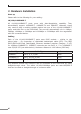
3.4.1 Connecting End Node or Switch
1. Place the GSD-804P on a smooth surface or fasten the mounting brackets
purchased separately with the provided screws in a standard 19” rack.
2. Connect the power cord to the power inlet socket of the GSD-804P and the
other end into the local power source outlet. When the Switch receives power,
the Power LED should remain solid Green.
3. Connect the other switch or PC to one port of the GSD-804P using Category
5e/6 UTP/STP cabling.
4. Connect another switch or PC to the other port of GSD-804P by following the
same process as described in Step 3.
802.3at PoE
IP Camera
802.3af PoE
VoIP Phone
NN
PoE PoE PoE PoE
Power
AC
Power Line (AC)
AC
1000BASE-T UTP
PoE
1000BASE-T UTP with PoE
2.4GHz 802.11n
N
802.3af PoE
VoIP Phone
802.3at PoE
Wireless AP
LAN / PCs
10/100/1000BASE-T Data
GSD-804P
Figure 3-4: End Node or Switch Connection