8-Port 10/100/1000T Gigabit Ethernet Switch with 4-Port 802.
Trademarks Copyright © PLANET Technology Corp. 2018. Contents are subject to revision without prior notice. PLANET is a registered trademark of PLANET Technology Corp. All other trademarks belong to their re-spective owners.
Energy Saving Note of the Device This power required device does not support Standby mode operation. For energy saving, please remove the power cable to disconnect the device from the power circuit. In view of saving the energy and reducing the unnecessary power consumption, it is strongly suggested to remove the power connection for the device if this device is not intended to be active.
Table of Contents 1. Introduction................................................................................................ 5 1.1 Package Contents................................................................................. 5 1.2 Product Description............................................................................... 5 1.3 Features.............................................................................................. 6 1.4 Specifications...........................................
1. Introduction 1.1 Package Contents Please unpack the box of the device carefully, and the box should contain the following items: GSD-804P x 1 Attachment Screws x 8 Rubber Feet x 4 User’s Manual x 1 Power Cord x 1 19" Rack-mounting Brackets x 1 If any of these pieces are missing or damaged, please contact your dealer immediately. 1.
1.3 Features Physical Port zz 4 10/100/1000BASE-T Gigabit Ethernet IEEE 802.3at PoE+ RJ45 copper ports (Port-1 to Port-4) zz 4 10/100/1000BASE-T Gigabit Ethernet non-PoE RJ45 copper port (Port-5 to Port-8) Power over Ethernet zz Complies with IEEE 802.3af/at Power over Ethernet end-span PSE zz Up to 4 ports of IEEE 802.3af/802.3at devices powered zz Supports PoE Power up to 30.
1.4 Specifications Model GSD-804P Hardware Specifications Hardware Version 3 10/100/1000BASE-T MDI/MDIX Ports 8 PoE Injector Port 4 ports with 802.3af/at PoE injector function with Port-1 to Port-4 Switch Architecture Store-and-Forward Switch Fabric 16Gbps/non-blocking Switch Throughput@64 bytes 11.9Mpps@64 bytes MAC Address Table 4K entries, automatic source address learning and aging Maximum Frame Size 9K bytes Flow Control IEEE 802.
Power over Ethernet PoE Standard IEEE 802.3af Power over Ethernet/PSE IEEE 802.3at Power over Ethernet Plus/PSE PoE Power Supply Type End-span PoE Power Output Per port 55V DC, 560mA. max. 30.8 watts Power Pin Assignment 1/2(+), 3/6(-) PoE Power Budget 60 watts Max. Number of Class 2 PDs 4 Max. Number of Class 3 PDs 4 Max. Number of Class 4 PDs 2 Standards Conformance Regulatory Compliance FCC Part 15 Class A, CE Standards Compliance IEEE IEEE IEEE IEEE IEEE IEEE IEEE 802.3 10BASE-T 802.
2. Hardware Description These switches provide three different running speeds – 10Mbps, 100Mbps and 1000Mbps, and automatically distinguish the speed of the incoming connection. This section describes the hardware features of the GSD-804P. For easier management and control of the GSD-804P, familiarize yourself with its display indicators and ports. Front panel illustrations in this chapter display the unit LED indicators.
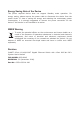
Default PoE Mode DIP PoE IP Camera GSD-804P PoE AC Power 100 meters (328 feet) PoE 1000BASE-T UTP with PoE AC Power Line (AC) Extend PoE Mode DIP PoE IP Camera GSD-804P PoE AC Power 250 meters (820 feet) PoE 10BASE-T UTP with PoE AC Power Line (AC) 2.1.1 LED Indicators System LED Color PWR Green Lights to indicate that the Switch has power. Function POE MAX Green Lights to indicate that the PoE usage is full.
2.2 Rear Panel The rear panel of the GSD-804P indicates an AC inlet power socket, which accepts input power from 100 to 240V AC, 50-60Hz. 100-240V AC 50/60Hz, 2.5A max. Figure 2-2: GSD-804P Switch Rear Panel Power Note 1. The device is a power-required device which means it will not work till it is powered. If your networks should be active all the time, please consider using UPS (Uninterrupted Power Supply) for your device. It will prevent you from network data loss or network downtime 2.
3. Hardware Installation Start up Please refer to the following for your cabling: 10/100/1000BASE-T All 10/100/1000BASE-T ports come with Auto-Negotiation capability. They automatically support 1000BASE-T, 100BASE-TX and 10BASE-T networks. Users only need to plug a working network device into one of the 10/100/1000BASE-T ports, and then turn on the GSD-804P. The port will automatically run in 10Mbps, 20Mbps, 100Mbps or 200Mbps and 1000Mbps or 2000Mbps after the negotiation with the connected device.
3.1 Desktop Installation To install the GSD-804P on desktop, simply follow the following steps: Step 1: Attach the rubber feet to the recessed areas on the bottom of the GSD804P, as shown in Figure 3-1. 8-Port 10/1 Ethernet 00/1000Mbp s with 4-Po Switch rt 802.
3.2 Rack Mounting To install the GSD-804P in a 19-inch standard rack, follow the instructions described below. Step 1: Place your GSD-804P on a hard flat surface, with the front panel positioned towards your front side. Step 2: Attach a rack-mount bracket to each side of the GSD-804P with supplied screws attached to the package. Figure 3-2 shows how to attach brackets to one side of the GSD-804P. 8-Port 10/1 Ethernet 00/1000Mbp s with 4-Po Switch rt 802.
Step 6: Proceed with Steps 4 and 5 of session 3.1 Desktop Installation to connect the network cabling and supply power to your Switch. 3.3 Wall Mounting Installation Step 1: Please find the wall that can mount the GSD-804P. Step 2: Install two screws on the wall. Step 3: Hang the GSD-804P on the screws from the wall. Step 4: Repeat step 5 of Desktop Installation for power supply to the GSD804P. 150mm 50/60Hz, 1.
3.4 Product Application 3.4.1 Connecting End Node or Switch 1. Place the GSD-804P on a smooth surface or fasten the mounting brackets purchased separately with the provided screws in a standard 19” rack. 2. Connect the power cord to the power inlet socket of the GSD-804P and the other end into the local power source outlet. When the Switch receives power, the Power LED should remain solid Green. 3. Connect the other switch or PC to one port of the GSD-804P using Category 5e/6 UTP/STP cabling. 4.
Cable Distance for Switch The cable distance between the GSD-804P and PC should not exceed 100 meters for UTP/STP cable. Make sure the wiring is correct Category 3/4/5 cable can be used in 10Mbps operation. To reliably operate your network at 100Mbps or 1000Mbps, you must use an Unshielded Twisted-Pair (UTP) Category 5/5e/6 cable, or better Data Grade cabling. While Category 3 or 4 cables may initially seem to work, it will soon cause data loss. Note 3.4.
3.5 Power over Ethernet Powered Device Voice over IP phones 3~5 Watts Enterprise can install PoE VoIP Phone, ATA and other Ether-net/non-Ethernet end devices in the central area where UPS is installed for uninterruptible power system and power control system. Wireless LAN Access Points 6~12 Watts Museums, airports, hotels, scenic places, campuses, factories, and warehouses can install access points anywhere with no hesitation.
4. Power over Ethernet Overview What is PoE? PoE is an abbreviation of Power over Ethernet. The PoE technology means a system safely transmits both power and data on Ethernet UTP cable. The IEEE standard for PoE technology requires Category 5 cable or higher for high power PoE levels, but can operate with Cat3 cable for low power levels.
Powered Device A powered device (PD) is a device powered by a PSE and thus consumes energy. Examples include wireless access points, IP phones, and IP cameras. Many PDs have an auxiliary power connector for an optional, external power supply. Depending on the PD design, some, none, or all power can be supplied from the auxiliary port, with the auxiliary port sometimes acting as backup power in case of PoE supplied power failure.
The data pairs are used. Since Ethernet pairs are transformers coupled at each end, it is possible to apply DC power to the center tap of the isolated transformer without upsetting the data transfer. In this mode of operation, the pair on pins 3 and 6 and the pair on pins 1 and 2 can be of either polarity.
5. Troubleshooting This chapter contains information to help you solve issues. If the GSD-804P is not functioning properly, make sure the GSD-804P was set up according to instructions in this manual. Q1: The Link LED is not lit. Solution: Check the cable connection and also try to swap one new cable. Q2: 1000BASE-T port link LED is lit, but the traffic is irregular. Solution: Make sure the attached device is not set to full duplex. Some devices use a physical or software switch to change duplex modes.
Appendix A Networking Connection A.1 Switch's Data RJ45 Pin Assignments - 1000Mbps, 1000BASE-T PIN NO MDI MDI-X 1 BI_DA+ BI_DB+ 2 BI_DA- BI_DB- 3 BI_DB+ BI_DA+ 4 BI_DC+ BI_DD+ 5 BI_DC- BI_DD- 6 BI_DB- BI_DA- 7 BI_DD+ BI_DC+ 8 BI_DD- BI_DC- Implicit implementation of the crossover function within a twisted-pair cable, or at a wiring panel, while not expressly forbidden, is beyond the scope of this standard. A.
The standard cable, RJ45 pin assignment The standard RJ45 receptacle/connector There are 8 wires on a standard UTP/STP cable and each wire is color-coded.