User's Manual GSD-800S GSD-802S 8-Port Gigabit Web Smart Ethernet Switch GSD-802PS 8-Port Gigabit Web Smart PoE Switch
User’s Manual of GSD-800S / GSD-802S / GSD-802PS Trademarks Copyright © PLANET Technology Corp. 2007. Contents subject to which revision without prior notice. PLANET is a registered trademark of PLANET Technology Corp. All other trademarks belong to their respective owners.
User’s Manual of GSD-800S / GSD-802S / GSD-802PS TABLE OF CONTENTS 1. INTRODUCTION............................................................................................................................................................. 1 PACKAGE CONTENTS .......................................................................................................................................................... 1 HOW TO USE THIS MANUAL ........................................................................
User’s Manual of GSD-800S / GSD-802S / GSD-802PS 4.8.1 IGMP Snooping Configuration........................................................................................................................... 47 4.8.2 IGMP Snooping Status...................................................................................................................................... 48 4.8.3 Multicast Group Table ...............................................................................................................
User’s Manual of GSD-800S / GSD-802S / GSD-802PS 1.
User’s Manual of GSD-800S / GSD-802S / GSD-802PS Product Features Physical Port GSD-800S z 8-Port 10/100/1000Base-T RJ-45 Copper ports. GSD-802S z 8-Port 10/100/1000Base-T RJ-45 Copper with 2 Shared SFP / mini-GBIC slots GSD-802PS z 8-Port 10/100/1000Base-T RJ-45 Copper with 2 Shared SFP / mini-GBIC slots Generic Features z Comply with IEEE 802.3, 10Base-T, IEEE 802.3u, 100Base-TX, IEEE 802.3ab,1000Base-T, IEEE 802.
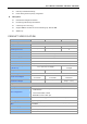
User’s Manual of GSD-800S / GSD-802S / GSD-802PS z LED easy PoE status Monitoring z Power feeding on/off and priority configuration Management z Remote Web management interface z Firmware upgrade through web interface z Cable Diagnostics technology z Support SNMPv1 with RFC-1213/1573-Interface group, Ethernet MIB z SNMP Trap PRODUCT SPECIFICATION Model GSD-800S GSD-802S GSD-802PS Hardware Specification 8-Port 10/100/1000Base-T Auto MDI/MDI-X Copper Ports SFP/mini-GBIC slot - 2 2 P
User’s Manual of GSD-800S / GSD-802S / GSD-802PS RFC-1573-Interface MIB RFC-2819 RMON MIB (Group 1) Standards Conformance EMI Safety Network Standards FCC Class A, CE IEEE 802.3 Ethernet IEEE 802.3u Fast Ethernet IEEE 802.3ab Gigabit Ethernet IEEE 802.3z Gigabit Ethernet, 1000Base-SX/LX IEEE 802.1q Tagged VLAN IEEE 802.1w Rapid Spanning Tree IEEE 802.1X Port-Based Authentication IEEE 802.3ad Link Aggregation Control Protocol IEEE 802.3x Full-Duplex flow control IEEE 802.
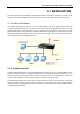
User’s Manual of GSD-800S / GSD-802S / GSD-802PS 2. INSTALLATION This section describes the functionalities of Gigabit Ethernet Switch’s components and guides how to install it on the desktop or shelf. Basic knowledge of networking is assumed. Please read this chapter completely before continuing. 2.1 Product Description The PLANET Gigabit Ethernet Switch is an 8-Port 10/100/1000Mbps Web Smart Gigabit Ethernet Switch with non-blocking wire-speed performance.
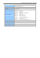
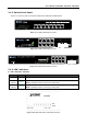
User’s Manual of GSD-800S / GSD-802S / GSD-802PS 2.1.2 Switch Front Panel Figure 2-1 & 2-2 & 2-3 shows a front panel of GSD-800S / GSD-802S and GSD-802PS. 1 1 2 3 4 5 6 LNK 7 8 2 3 4 5 6 7 8 1000 10/100 ACT Figure 2-1 PLANET GSD-800S Front Panel Figure 2-2 PLANET GSD-802S Front Panel Figure 2-3 PLANET GSD-802PS Front Panel 2.1.3 LED Indicators ■ LED of GSD-800S / GSD-802S LED Color Function PWR Green Lights to indicate that the Switch is powered on.
User’s Manual of GSD-800S / GSD-802S / GSD-802PS ■ LED of GSD-802PS LED Color Function PWR Green Lights to indicate that the Switch is powered on. PoE In Use Orange 1000 LNK/ACT 10/100 LNK/ACT Green Green Lights to indicate the port is providing 48VDC in-line power. Lights to indicate that the Switch is successfully connecting to the network at 1000Mbps. Blinks to indicate the Switch is receiving or sending data.
User’s Manual of GSD-800S / GSD-802S / GSD-802PS Power Notice: 1. The device is a power-required device, it means, it will not work till it is powered. If your networks should active all the time, please consider using UPS (Uninterrupted Power Supply) for your device. It will prevent you from network data loss or network downtime. 2.
User’s Manual of GSD-800S / GSD-802S / GSD-802PS 2.2.2 Rack Mounting To install the switch in a 19-inch standard rack, please follows the instructions described below. #Notice: Optional rack-ear for 10-inch cabinet rack mounting (RKE-10A) and 19-inch cabinet rack mounting (RKE-10B) is available upon request. Step1: Place the Gigabit Ethernet Switch on a hard flat surface, with the front panel positioned towards the front side.
User’s Manual of GSD-800S / GSD-802S / GSD-802PS Figure 2-9 Mounting the Gigabit Ethernet Switch in a Rack Step6: Proceeds with the steps 4 and steps 5 of session 2.2.1 Desktop Installation to connect the network cabling and supply power to the Gigabit Ethernet Switch. 2.2.3 Installing the SFP transceiver The sections describe how to insert an SFP transceiver into an SFP slot. The SFP transceivers are hot-pluggable and hot-swappable.
User’s Manual of GSD-800S / GSD-802S / GSD-802PS Connect the fiber cable 1. Attach the duplex LC connector on the network cable into the SFP transceiver. 2. Connect the other end of the cable to a device – switches with SFP installed, fiber NIC on a workstation or a Media Converter.. 3. Check the LNK/ACT LED of the SFP slot on the front of the Gigabit Ethernet Switch. Ensure that the SFP transceiver is operating correctly. 4. Check the Link mode of the SFP port if the link failed.
User’s Manual of GSD-800S / GSD-802S / GSD-802PS 3. SWITCH MANAGEMENT This chapter describes how to manage the Gigabit Ethernet Switch. Topics include: - Overview - Management methods - Assigning an IP address to the Gigabit Ethernet Switch - Logging on to the Gigabit Ethernet Switch 3.1 Overview This chapter gives an overview of switch management. The Gigabit Ethernet Switch provides a simply WEB browser interface.
User’s Manual of GSD-800S / GSD-802S / GSD-802PS The Gigabit Ethernet Switch must have an Internet Protocol (IP) address accessible for the remote host. 3.2.2 Login the Switch Before you start configure the Gigabit Ethernet Switch, please note the Gigabit Ethernet Switch is configured through an Ethernet connection, make sure the manager PC must be set on same the IP subnet address. For example, the default IP address of the Gigabit Ethernet Switch is 192.168.0.
User’s Manual of GSD-800S / GSD-802S / GSD-802PS 4. CONFIGURATION The Gigabit Ethernet Switch provide Web interface for Switch smart function configuration and make the Switch operate more effectively - They can be configured through the Web Browser. A network administrator can manage and monitor the Gigabit Ethernet Switch from the local LAN. This section indicates how to configure the Gigabit Ethernet Switch to enable its smart function.
User’s Manual of GSD-800S / GSD-802S / GSD-802PS ◆ IGMP Snooping - Enables or disables IGMP Snooping on the device to filter the multicast stream. ◆ Quality of Service – Mapping the packet level to classify the packets priority. ◆ 802.1X Management – Specify ports with network access control. ◆ MAC Address – Dynamic Address Table / Static MAC Address. ◆ Tools – Reboot / Factory Reset / Firmware Update / Configuration Upload / Ping / Cable Diagnostic/ Web Smart function.
User’s Manual of GSD-800S / GSD-802S / GSD-802PS 4.2 System 4.2.1 System Info The System Info page provides information for the current device information. System Info page helps a switch administrator to identify the firmware / hardware version and IP subnet address / DHCP server IP address. The screen in Figure 4-2 appears. Figure 4-2 System Information screen The page includes the following fields: • MAC Address Specifies the device MAC address.
User’s Manual of GSD-800S / GSD-802S / GSD-802PS be released. 4.2.2 Misc Configuration The Misc Configuration includes the System name, Location name, Login Timeout, IP Address, Subnet Mask and Gateway. Through the Web Switch Utility, you can easily recognize the device by using the System Name and the Location Name.
User’s Manual of GSD-800S / GSD-802S / GSD-802PS Inactivity Timeout Specifies a time period for the user login. The web interface will be auto logout if there’re no actions from the login user. The default value is 300 seconds; 0 means no inactivity time limit. SNMP Enable Enable or Disable the SNMP function of the device. While set to enable, the manager could remotely get the interface status and received the traps information.
User’s Manual of GSD-800S / GSD-802S / GSD-802PS 4.3 Port Configuration This function allows displaying each port’s status. The Link Status in the screen displays the current connection speed and duplex mode; else this function will show down when the port is disconnected. Press the “Refresh” button to renew the screen. The screen in Figure 4-4 appears.
User’s Manual of GSD-800S / GSD-802S / GSD-802PS • Flow Control Allow Enable or Disable flow control for selected port. • Enable – 802.3x flow control is enabled on Full-Duplex mode or Backpressure is enabled on Half-Duplex mode. • Disable – No flow control or backpressure function on no matter Full-Duplex or Half-Duplex mode. • Port Description #Note: Can key in the description for the port. When set each port to run at 100M Full, 100M Half, 10M Full, and 10M Half-speed modes.
User’s Manual of GSD-800S / GSD-802S / GSD-802PS 4.4 Port Mirroring This function provide to monitoring network traffic that forwards a copy of each incoming or outgoing packet from one port of a network Switch to another port where the packet can be studied. It enables the manager to keep close track of switch performance and alter it if necessary. The Port Mirroring screen in Figure 4-5 appears.
User’s Manual of GSD-800S / GSD-802S / GSD-802PS 4.5 VLANs A Virtual LAN (VLAN) is a logical network grouping that limits the broadcast domain. It allows you to isolate network traffic so only members of the VLAN receive traffic from the same VLAN members. Basically, creating a VLAN from a switch is logically equivalent of reconnecting a group of network devices to another Layer 2 switch. However, all the network devices are still plug into the same switch physically.
User’s Manual of GSD-800S / GSD-802S / GSD-802PS 4.5.1 VLAN Membership This function group individual ports into a small “Virtual” network of their own to be independent of the other ports. The screen in Figure 4-6 appears. Figure 4-6 VLAN Membership screen The page includes the following items: • VLAN ID Specify the VLAN Identifier for the new VLAN. (You can only enter data in this field when you are creating a new VLAN.) The range of the VLAN ID is (1 to 4094).
User’s Manual of GSD-800S / GSD-802S / GSD-802PS Figure 4-7 Add a VLAN screen Figure 4-8 VLAN Member Setup screen 4.5.1.2 Modify the VLAN Group Member Once you want to modify the existence VLAN Group member or delete a existence VLAN Group. Refer to the following steps. 1. To modify the members of an existence VLAN Group, check the VLAN Group ID and press “Modify” button. The ID VLAN Setup screen will pop out. 2.
User’s Manual of GSD-800S / GSD-802S / GSD-802PS Figure 4-9 VLAN Group – member modify and delete VLAN Group screen #Notice: Once the VLAN Group be deleted, the Ports with the PVID set to this VLAN Group have to re-configure the PVID.
User’s Manual of GSD-800S / GSD-802S / GSD-802PS 4.5.2 Per Port Configuration The VLAN per Port Configuration page contains fields for managing ports that are part of a VLAN. The port default VLAN ID (PVID) is configured on the VLAN Port Configuration page. All untagged packets arriving to the device are tagged by the ports PVID. The screen in Figure 4-10 appears. Figure 4-10 VLAN Port Configuration The page includes the following fields: • VLAN Type There’re two VLAN mode support – 802.
User’s Manual of GSD-800S / GSD-802S / GSD-802PS Disabled - all frames are forwarded in accordance with the 802.1Q VLAN bridge specification. The factory default is disabled. • Acceptable Frame Types Specifies the types of frames that may be received on this port. The options are 'All' and 'Tagged only'. • All- untagged frames or priority tagged frames received on this port are accepted and assigned the value of the Port VLAN ID for this port.
User’s Manual of GSD-800S / GSD-802S / GSD-802PS 4.5.3 VLAN setting example: 4.5.3.1 Two separate 802.1Q VLAN The diagram shows how the switch handle Tagged and Untagged traffic flow for two VLANs. VLAN Group 2 and VLAN Group 3 are separated VLAN. Each VLAN isolate network traffic so only members of the VLAN receive traffic from the same VLAN members. The screen in Figure 4-11 appears and Table 4-1 describes the port configuration of switch.
User’s Manual of GSD-800S / GSD-802S / GSD-802PS Untagged packet entering VLAN 3 1. While [PC-4] transmit an untagged packet enters Port-4, the switch will tag it with a VLAN Tag=3. [PC-5] and [PC-6] will received the packet through Port-5 and Port-6. 2. While the packet leaves Port-5, it will be stripped away it tag becoming an untagged packet. 3. While the packet leaves Port-6, it will keep as a tagged packet with VLAN Tag=3.
User’s Manual of GSD-800S / GSD-802S / GSD-802PS Figure 4-13 Assign VLAN members for VLAN 2 and VLAN 3 Remember to remove the Port 1 – Port 6 from VLAN 1 membership, since the Port 1 – Port 6 had been assigned to VLAN 2 and VLAN 3. Figure 4-14 Remove specify ports from VLAN 1 member #Notice: It’s import to remove the VLAN members from VLAN 1 configuration. Or the ports would become overlap setting.
User’s Manual of GSD-800S / GSD-802S / GSD-802PS 3. Assign PVID for each port: Port-1,Port-2 and Port-3 : PVID=2 Port-4,Port-5 and Port-6 : PVID=3 Port-7~Port-8: PVID=1 4. Enable VLAN Tag for specific ports Link Type: Port-3 (VLAN-2) and Port-6 (VLAN-3) The Per Port VLAN configuration in Figure 4-15 appears.
User’s Manual of GSD-800S / GSD-802S / GSD-802PS 4.5.3.2 Two VLANs with overlap area Follow the example of 4.5.3.1. There’re two exist separate VLANs – VLAN 2 and VLAN 3, and the PCs of each VLANs are not able to access each other of different VLANs. But they all need to access with the same server. The screen in Figure 4-16 appear. This section will show you how to configure the port for the server – that could be accessed by both VLAN 2 and VLAN 3.
User’s Manual of GSD-800S / GSD-802S / GSD-802PS 3. Define a VLAN 1 as a “Public Area” that overlapping with both VLAN 2 members and VLAN 3 members. Figure 4-18 VLAN 1 – The public area member assign 4. Setup Port-7 with “PVID=1” at VLAN per Port Configuration page. The screen in Figure 4-19 appears.
User’s Manual of GSD-800S / GSD-802S / GSD-802PS That is, although the VLAN 2 members: Port-1 to Port-3 and VLAN 3 members: Port-4 to Port-6 also belong to VLAN 1. But with different PVID settings, packets form VLAN 2 or VLAN 3 is not able to access to the other VLAN. 4.5.3.3 VLAN Trunking between two 802.1Q aware switch The most cases are used for “Uplink” to other switches. VLANs are separated at different switches, but they need to access with other switches within the same VLAN group.
User’s Manual of GSD-800S / GSD-802S / GSD-802PS Figure 4-22 Add VLAN Trunk port to each VLAN 3. Repeat Step 1 and 2, setup the VLAN Trunk port at the partner switch. 4. To add more VLANs to join the VLAN trunk, repeat Step 2 to assign the Trunk port to the VLANs.
User’s Manual of GSD-800S / GSD-802S / GSD-802PS 4.6 Rapid Spanning Tree Spanning Tree Protocol (STP) provides tree topography for any arrangement of bridges. STP also provides one path between end stations on a network, eliminating loops. Rapid Spanning Tree Protocol (RSTP) - While Classic Spanning Tree guarantees preventing L2 forwarding loops in a general network topology, convergence can take up to 30-60 seconds. The convergence time is considered too long for many applications.
User’s Manual of GSD-800S / GSD-802S / GSD-802PS 4.6.1 RSTP System Configuration The “RSTP System Configuration” table allows configuring the spanning tree parameters. Figure 4-24 RSTP System Configuration The page includes the following fields: • System Priority Specifies the bridge priority value. When switches or bridges are running STP, each is assigned a priority. After exchanging BPDUs, the switch with the lowest priority value becomes the Root Bridge.
User’s Manual of GSD-800S / GSD-802S / GSD-802PS stations, avoiding and eliminating loops. #Notice: • Max Age -. The value lies between 6 and 40, with the value being less than or equal to "(2 * Bridge Forward Delay) - 1" and greater than or equal to "2 * ( Bridge Hello Time +1)". The default value is 20. • Hello Time - The value being less than or equal to "(Bridge Max Age / 2) - 1". The default hello time value is 2.
User’s Manual of GSD-800S / GSD-802S / GSD-802PS - Ethernet – 2000000. - Fast Ethernet - 200000. - Gigabit Ethernet - 20000. 4.6.3 RSTP Status The RSTP Status page display the current STP bridge , roor bridge and per port stp status. To access RSTP Status screen and perform the following procedure: 1. Click Status -> RSTP Status 2. The “RSTP VLAN Bridge Overview” and “RSTP Port Status” screen is displayed as in Figure 4-26.
User’s Manual of GSD-800S / GSD-802S / GSD-802PS • Hello Time Minimum time between transmissions of Configuration BPDUs. • Max Age Path Cost to the Designated Root for the spanning tree. • Forward Delay Derived value of the Root Port Bridge Forward Delay parameter. • Topology Specifies the Tolology change status of the current operation. If no topology change happened, the table show “Steady”. • Root Id Identifies the Root Bridge priority and MAC address.
User’s Manual of GSD-800S / GSD-802S / GSD-802PS • Disabled -- The port link is currently down. • Blocking -- The port is currently blocked and cannot be used to forward traffic or learn MAC addresses. Blocking is displayed when Classic STP is enabled. • Listening -- The port is currently in the listening mode. The port cannot forward traffic nor can it learn MAC addresses. • Learning -- The port is currently in the learning mode. The port cannot forward traffic however it can learn new MAC addresses.
User’s Manual of GSD-800S / GSD-802S / GSD-802PS 4.7 Link Aggregation Port Aggregation optimizes port usage by linking a group of ports together to form a single Link Aggregated Groups (LAGs). Port Aggregation multiplies the bandwidth between the devices, increases port flexibility, and provides link redundancy. Each LAG is composed of ports of the same speed, set to full-duplex operations.
User’s Manual of GSD-800S / GSD-802S / GSD-802PS The page includes the following fields: • Port Indicate port 1 to port 8. • Normal While a port is checked as “Normal”, the port is not joining to any Static Trunk Group. • Group Specify the Joined Trunk Group. There’re maximum 4 trunk groups per system. With different switch model, the maximum number of ports are as follow: A port can be assigned to only one Trunk Group. 4.7.
User’s Manual of GSD-800S / GSD-802S / GSD-802PS The page includes the following fields: • Port Indicate port 1 to port 8. • Protocol Enable To Enable or disable the LCAP protocol on a selected port. Once the LACP protocol be enabled, the system will start transmit the LACP control packets and exchange with another LACP aware switch. If the linked switch didn’t support LACP, then the aggregated link will not be established. • Key Value The Key Value will be filed in the LACP control packets.
User’s Manual of GSD-800S / GSD-802S / GSD-802PS 4.7.3 LACP Status The LACP Status page display the current LACP aggregation Groups and LACP Port status. To open LACP Status screen perform the folling: 1. Click Status -> LACP Status. 2. The “LACP Aggregation Overview” and “LACP Port Status” screen is displayed as in Figure 4-31. Figure 4-31 LACP Status LACP Aggregation Overview Table The LACP Aggregation Overview Table lists the active LACP ports and mapped Group.
User’s Manual of GSD-800S / GSD-802S / GSD-802PS The Color and ID legend Down 0 Blocked Port Blocked by RSTP. Number is Partner port number if other switch has LACP enabled. 0 Learning Port Learning by RSTP. 0 Port link down. Forwarding Port link up and forwarding frames. Forwarding Port link up and forwarding by RSTP. Number is Partner port number if other switch has LACP enabled.
User’s Manual of GSD-800S / GSD-802S / GSD-802PS 4.8 IGMP Snooping The Internet Group Management Protocol (IGMP) lets host and routers share information about multicast groups memberships. IGMP snooping is a switch feature that monitors the exchange of IGMP messages and copies them to the CPU for feature processing. The overall purpose of IGMP Snooping is to limit the forwarding of multicast frames to only ports that are a member of the multicast group. 4.8.
User’s Manual of GSD-800S / GSD-802S / GSD-802PS Enabled periodically check the multicast group for members that are no longer active. In the case where there is more than one multicast router on a sub network, one router is elected as the ‘queried’. This router then keeps track of the membership of the multicast groups that have active members. The information received from IGMP is then used to determine if multicast packets should be forwarded to a given sub network or not.
User’s Manual of GSD-800S / GSD-802S / GSD-802PS The page includes the following fields: • VLAN ID Identifies a VLAN and contains information about the Multicast group configuration. • Querier Display the current status of IGMP Querier on the device. Active – The IGMP Query function had been enabled on the device and played as a main Querier within a subnet domain. Within a network domain, there will be only one IGMP Querier. While two or more Querier exist, only one Querier operation by election.
User’s Manual of GSD-800S / GSD-802S / GSD-802PS 4.8.3 Multicast Group Table The Multicast Group page displays the ports attached to the Multicast service group in the Ports tables. The Port a tables also reflect the manner in which the port joined the Multicast group. Ports can be added either to existing groups or to new Multicast service groups. The Bridge Multicast Group page permits new Multicast service groups to be created.
User’s Manual of GSD-800S / GSD-802S / GSD-802PS 4.9 Quality of Service Quality of Service (QoS) is an advanced traffic prioritization feature that allows you to establish control over network traffic. QoS enables you to assign various grades of network service to different types of traffic, such as multi-media, video, protocol-specific, time critical, and file-backup traffic. QoS reduces bandwidth limitations, delay, loss, and jitter.
User’s Manual of GSD-800S / GSD-802S / GSD-802PS Figure 4-37 QoS Configuration screen 4.9.1 802.1p QoS Mode QoS settings allow customization of packet priority in order to facilitate delivery of data traffic that might be affected by latency problems. The IEEE 802.1p Priority specification uses 8 priority levels to classify data packets. The screen in Figure 4-38 and Figure 4-39 appears. Figure 4-38 802.
User’s Manual of GSD-800S / GSD-802S / GSD-802PS Figure 4-39 Prioritize Traffic screen The page includes the following fields: • Prioritize Traffic The draw menu allows customization of 802.1p to Traffic classifiers. Total 5 selections for the Prioritize Traffic. • Custom – Manual mapping the 802.1p priority to the 4-level queues. Setup at the next table. • All Low Priority - mapping all 802.1p tagged packets to Queue 0 • All Normal Priority - mapping all 802.
User’s Manual of GSD-800S / GSD-802S / GSD-802PS 4.9.2 DSCP QoS Mode DiffServ Code Point (DSCP) - is the traffic prioritization bits within an IP header that are encoded by certain applications and/or devices to indicate the level of service required by the packet across a network. The DSCP Configuration page provides fields for defining output queue to specific DSCP fields. Select the QoS mode to DSCP, the DSCP to queue mapping configuration page appears, as the Figure 4-40 shows.
User’s Manual of GSD-800S / GSD-802S / GSD-802PS 4.10 802.1X Management The PLANET Gigabit Ethernet Switch supports IEEE 802.1X Port-base network access control and RADIUS server authentication to enhance the host link more security. An 802.1X Infrastructure is composed of three major components: Authenticator, Authentication server, and Supplicant. Authentication server – (RADIUS Server): An entity that provides an authentication service to an authenticator.
User’s Manual of GSD-800S / GSD-802S / GSD-802PS 8. The client and RADIUS server derive encryption keys. 9. The RADIUS server sends Web-Smart Switch a RADIUS ACCEPT message. 10. Web-Smart Switch sends the client an EAP Success message along with the broadcast key and key length. This section is to control the access of the switch, includes the user access and management control. The 802.1X Management page contains links to the following topics: • RADIUS Server Configuration • Port Access Control 4.10.
User’s Manual of GSD-800S / GSD-802S / GSD-802PS The RADIUS Server configuration table includes the following fields: • Mode To Enable/Disable the port access control administrative mode. This selector lists the two options for administrative mode: enable and disable. The default value is disabled. • RADIUS Server IP The IP address of the RADIUS server being added. • RADIUS UDP Port The UDP port used by this server. The valid range is 0 - 65535. The default UDP Port No.
User’s Manual of GSD-800S / GSD-802S / GSD-802PS 4.10.2 Port Access Control This table is to configure the per port network access control setting. By drawing and select the menu bar to define the port control type. The screen in Figure 4-44 and Figure 4-45 appears. Figure 4-44 Per Port network access control configure table Figure 4-45 802.
User’s Manual of GSD-800S / GSD-802S / GSD-802PS required to press the Submit button for the action to occur. • Force Reinitialize This button begins the re-initialization sequence on the selected port. This button is only selectable if the control mode is 'auto'. If the button is not selectable, it will be grayed out. Once this button is pressed, the action is immediate. It is not required to press the Submit button for the action to occur. • Statistics This button redirect to the “802.
User’s Manual of GSD-800S / GSD-802S / GSD-802PS 4.11 MAC Addresses 4.11.1 Dynamic Address Table Use this page to set the Address Ageing Timeout for the MAC Address database, and to display information about entries in the MAC Address database. These entries are used by the transparent bridging function to determine how to forward a received frame. The screen in Figure 4-47 appears.
User’s Manual of GSD-800S / GSD-802S / GSD-802PS will be forward to the specify port. • MAC-Address Specifies the MAC address for which the table is queried. 4.11.2 Static MAC Address The Static MAC Address page contains a list of static MAC addresses. Static Address can be added and removed from the page. In addition, several MAC Addresses can be defined for a single port. The screen in Figure 4-48 appears.
User’s Manual of GSD-800S / GSD-802S / GSD-802PS 4.12 Tools 4.12.1 Reboot The Reboot page enables the device to be rebooted from a remote location. Once the Reboot button be pressed, user have to re-login the WEB interface about 20 seconds later, the screen in Figure 4-49 appears. Figure 4-49 Reboot screen 4.12.2 Factory Reset The Factory Reset button can reset the Gigabit Ethernet Switch back to the factory default mode.
User’s Manual of GSD-800S / GSD-802S / GSD-802PS 4.12.3 Firmware Upgrade The Firmware Upgrade page contains fields for downloading system image files from the Local File browser to the device. To open Firmware Upgrade screen perform the folling: 1. Click Tools -> Firmware Upgrade. 2. The Firmware Upgrade screen is displayed as in Figure 4-51. 3. Click the “Browse” button of the main page, the system would pop up the file selection menu to choose firmware. 4.
User’s Manual of GSD-800S / GSD-802S / GSD-802PS 4.12.4 Configuration Upload This function allows backup and reload the current configuration of Switch to the local management station. The screen in Figure 4-53 appears. Configuration Upload: Upload the existed configuration file to the Switch. The configuration file had been saved at the local machine already. Configuration Download: Download the current configuration file of the switch to the local machine.
User’s Manual of GSD-800S / GSD-802S / GSD-802PS 2. Select on the configuration file then click “Upload”, the bottom of the browser shows the upload status. 3. After down, the main screen appears “Transfer Completed”. Configuration Download 1. Press the “Download” button to save the current configuration in manager workstation. The following screens in Figure 4-55 and 4-56 appear Figure 4-55 File Download screen 2. Chose the file save path in management workstation.
User’s Manual of GSD-800S / GSD-802S / GSD-802PS 4.12.5 Ping Use this screen to tell the switch to send a Ping request to a specified IP address. You can use this to check whether the switch can communicate with a particular IP station. Once you click the Apply button, the switch will send n pings and the results will be displayed below the configurable data.
User’s Manual of GSD-800S / GSD-802S / GSD-802PS #Notice: Be sure the target IP Address is within the same network subnet of the switch, or you had setup the correct gateway IP address. 4.12.6 Cable Diagnostics The Cable Diagnostics page contains fields for performing tests on copper cables. These functions have the ability to identify the cable length and operating conditions, and to isolate a variety of common faults that can occur on the Cat5 twisted-pair cabling.
User’s Manual of GSD-800S / GSD-802S / GSD-802PS • Pair The twist pair of the UTP cable. The pair groups as follow: A (Pin 1,2) B (Pin 3,6) C (Pin 4,5) D (Pin 7,8) • Length[m] When properly terminated, Cable Diagnostics reports the approximate cable length in meters of each of the four cable pair A, B, C, and D. • Status The cable test results. Possible values are: • Proper - The cable passed the test.
User’s Manual of GSD-800S / GSD-802S / GSD-802PS 4.12.7 Web Smart Function This function could provide you to define device indicate connect to each port on Web Smart Switch, the screen in Figure 4-60 appears. Figure 4-60 Web Smart Function Web Page screen The available options are shown as below: 1 PC 2 PC+VoIP 3 Switch 4 Router 5 AP 6 Server 7 Printer 8 Guest 9 Other The screen in Figure 4-61 appears and the setup procedure shown as below: 1.
User’s Manual of GSD-800S / GSD-802S / GSD-802PS 3. After setup completed, press “Apply” to save current configuration, the screen in Figure 4-62 appears.
User’s Manual of GSD-800S / GSD-802S / GSD-802PS This function also provides Apply for all ports option from Select a port function, the setup procedure shown as below: 1. Choose a device and check “Apply for all ports” from options of Select a port function, the screen in Figure 4-63appears. 2. Check any port then all port will be select; the screen in Figure 4-64 appears. 3. After setup completed, press “Apply” to save current configuration, the screen in Figure 4-69 appears.
User’s Manual of GSD-800S / GSD-802S / GSD-802PS Figure 4-64 Web Smart Function Web Page screen Figure 4-65 Web Smart Function Web Page screen
User’s Manual of GSD-800S / GSD-802S / GSD-802PS 4.13 Status Click on the “Status” to present the Switch status on this screen, it displays the following status: Port Statistics LACP Status RSTP Status IGMP Snooping Status Multicast Group Table 4.13.1 Port Statistics The Port Statistic Overview page displays the status of packet count from each port. The Port statistics overview screen in Figure 4-66 appears.
User’s Manual of GSD-800S / GSD-802S / GSD-802PS • Transmit Octets Number of octets of data (including those in bad packets) transmitted on the port. This object can be used as a reasonable estimate of Ethernet utilization. • Broad- and Multicast Number of packets transmitted on the port. Include the broadcast and multicast packets. • Error Packets The numbers of error packets transmit from the port. 4.13.
User’s Manual of GSD-800S / GSD-802S / GSD-802PS Figure 4-68 Login screen
User’s Manual of GSD-800S / GSD-802S / GSD-802PS 4.14 PoE Configuration ( GSD-802PS Only) The GSD-802PS is an 8 ports PoE Layer 2 Web Smart switch, it supports up to 8 ports PoE Power source (PSE) to supply PoE power for the connected Power Device (PD). Power Management: In a power over Ethernet system, operating power is applied from a power source (PSU-power supply unit) over the LAN infrastructure to powered devices (PDs), which are connected to ports.
User’s Manual of GSD-800S / GSD-802S / GSD-802PS Delivering Power [W] List each connected device power usage. Current [mA] List each connected device current usage. Priority Allow to assign the POE power provision priority on each POE port, the available values are o o o Low Medium High Also, from the Switch panel at the top side, the orange port icon shows that the port is connected to PDs with PoE output.
User’s Manual of GSD-800S / GSD-802S / GSD-802PS 5. SWITCH OPERATION 5.1 Address Table The Switch is implemented with an address table. This address table composed of many entries. Each entry is used to store the address information of some node in network, including MAC address, port no, etc. This information comes from the learning process of Ethernet Switch. 5.2 Learning When one packet comes in from any port, the Switch will record the source address, port no.
User’s Manual of GSD-800S / GSD-802S / GSD-802PS 5.5 Auto-Negotiation The STP ports on the Switch have built-in “Auto-negotiation”. This technology automatically sets the best possible bandwidth when a connection is established with another network device (usually at Power On or Reset). This is done by detect the modes and speeds at the second of both device is connected and capable of, both 10Base-T and 100Base-TX devices can connect with the port in either Half- or Full-Duplex mode.
User’s Manual of GSD-800S / GSD-802S / GSD-802PS A host will never send a report when it wants to leave a group (for version 1). A host will send a “leave” report when it wants to leave a group (for version 2). Multicast routers send IGMP queries (to the all-hosts group address: 224.0.0.1) periodically to see whether any group members exist on their sub networks. If there is no response from a particular group, the router assumes that there are no group members on the network.
User’s Manual of GSD-800S / GSD-802S / GSD-802PS 6. TROUBLESHOOTING This chapter contains information to help you solve problems. If the Switch is not functioning properly, make sure the Ethernet Switch was set up according to instructions in this manual. The Link LED is not lit Solution: Check the cable connection and remove duplex mode of the Switch.
User’s Manual of GSD-800S / GSD-802S / GSD-802PS APPENDIX A A.1 Switch‘s RJ-45 Pin Assignments 1000Mbps, 1000Base T Contact MDI MDI-X 1 BI_DA+ BI_DB+ 2 BI_DA- BI_DB- 3 BI_DB+ BI_DA+ 4 BI_DC+ BI_DD+ 5 BI_DC- BI_DD- 6 BI_DB- BI_DA- 7 BI_DD+ BI_DC+ 8 BI_DD- BI_DC- Implicit implementation of the crossover function within a twisted-pair cable, or at a wiring panel, while not expressly forbidden, is beyond the scope of this standard. A.
User’s Manual of GSD-800S / GSD-802S / GSD-802PS A.3 RJ-45 cable pin assignment 6 32 1 6 321 6 3 21 There are 8 wires on a standard UTP/STP cable and each wire is color-coded. The following shows the pin allocation and color of straight cable and crossover cable connection: Figure A-1: Straight-Through and Crossover Cable Please make sure your connected cables are with same pin assignment and color as above picture before deploying the cables into your network.