8-/16-/24-Port 10/100/1000T 802.
Copyright Copyright © 2018 by PLANET Technology Corp. All rights reserved. No part of this publication may be reproduced, transmitted, transcribed, stored in a retrieval system, or translated into any language or computer language, in any form or by any means, electronic, mechanical, magnetic, optical, chemical, manual or otherwise, without the prior written permission of PLANET.
FCC Interference Statement This equipment has been tested and found to comply with the limits for a Class A digital device, pursuant to Part 15 of the FCC Rules. These limits are designed to provide reasonable protection against harmful interference when the equipment is operated in a commercial environment. This equipment generates, uses, and can radiate radio frequency energy and, if not installed and used in accordance with the Instruction manual, may cause harmful interference to radio communications.
Table of Contents 1. Introduction................................................................................................ 5 1.1 Package Contents................................................................................. 5 1.2 Product Description............................................................................... 6 1.3 Features.............................................................................................10 1.4 Specifications.............................................
1. Introduction Thank you for purchasing PLANET 8/16/24-Port 10/100/1000T 802.3at PoE+ Gigabit SFP Ethernet Switch series, GSD-1222VHP, GSW-1820VHP and GSW-2620VHP. The descriptions of these models are shown below: GSD-1222VHP 8-Port 10/100/1000T 802.3at PoE + 2-Port Gigabit SFP + 2-Port Gigabit TP Ethernet Switch GSW-1820VHP 16-Port 10/100/1000T 802.3at PoE + 2-Port Gigabit SFP Ethernet Switch GSW-2620VHP 24-Port 10/100/1000T 802.3at PoE + 2-Port Gigabit SFP Ethernet Switch “802.
If any of these pieces are missing or damaged, please contact your dealer immediately; if possible, retain the carton including the original packing material, and use them again to repack the product in case there is a need to return it to us for repair. 1.2 Product Description Ideal High-performance Integration Solution for Secure IP Surveillance Infrastructure Particularly designed for the growing popular IP surveillance applications, PLANET GSD/GSW 802.
Just “Plug and Watch” for a Quick Solution The GSD/GSW 802.3at PoE+ Switch series is an ideal Plug and Watch Power over Ethernet solution which provides quick installation, real-time PoE work status monitoring and immediate troubleshooting through its unique LCD display to improve work efficiency and quality without any PC or software required. The GSD/GSW 802.3at PoE+ Switch series is equipped with 8/16/24 10/100/1000BASE-T ports featuring 30-watt 802.3at Power over Ethernet Plus (PoE+) copper interfaces.
Smart and Intuitive LCD Control The GSD/GSW 802.3at PoE+ Switch series provides an intuitive color panel on its front panel that facilitates the Ethernet management and PoE PD management.
Standard, VLAN and Extend Operation Modes Offered The GSD/GSW 802.3at PoE+ Switch series provides Standard, VLAN and Extend operation modes. The GSD/GSW 802.3at PoE+ Switch series operates as a normal IEEE 802.af/at PoE Switch in the Standard operation mode. The VLAN operation mode features the port-based VLAN function that can help to prevent the IP camera’s multicast or broadcast storm from influencing each other.
Flexible Extension Solution The two mini-GBIC slots built in the GSD/GSW 802.3at PoE+ Switch series are compatible with the 1000BASE-SX/LX SFP (Small Form-factor Pluggable) fiber transceiver, uplinked to the backbone switch and monitoring center in long distance. The distance can be extended from 550 meters (multi-mode fiber) to 10/20/30/40/50/60/70/120 kilometers (single-mode fiber or WDM fiber). They are well suited for applications within the enterprise data centers and distributions.
Power over Ethernet Complies with IEEE 802.3af/at Power over Ethernet end-span PSE Up to 8/16/24 ports of IEEE 802.
Hardware 12/19-inch desktop size, 1U height, rack mountable 2-inch color LCD with smart management functions LED indicators for system power, per port PoE ready and PoE activity, speed, Link/Act 1/3 silent fans to provide stable and efficient power performance Supports Energy-Efficient Ethernet (EEE) function (IEEE 802.3az) Supports contact discharge of ±6KV DC and air discharge of ±8KV DC for Ethernet ESD protection Supports ±6KV surge immunity 1.
LED Indicators System: Power (Green) 10/100/1000BASE-T RJ45 Interfaces: 10/100Mbps LNK/ACT (Red) 1000Mbps LNK/ACT (Green) PoE-in-Use (Amber) 1000BASE-X SFP Interfaces: 10/100Mbps LNK/ ACT (Red) 1000Mbps LNK/ ACT (Green) LCD Monitor (W x D) 40.6 x 30.5 mm, 2-inch Buttons Dimensions (W x D x H) Menu, Enter, Back, Up and Down 180 x 280 x 44mm (1U height) Enclosure Weight 1000BASE-X SFP Interfaces: LNK/ACT (Green) 233 x 440 x 44 mm (1U height) Metal 1.8kg 3.4kg 3.
Max. Number of Class 2 PDs 8 16 24 Max. Number of Class 3 PDs 8 16 23 Max. Number of Class 4 PDs 4 11 11 Standards Conformance Regulatory Compliance Standards Compliance FCC Part 15 Class A, CE IEEE IEEE IEEE IEEE IEEE IEEE IEEE IEEE 802.3 10BASE-T 802.3u 100BASE-TX 802.3ab Gigabit 1000BASE-T 802.3z Gigabit SX/LX 802.3x Flow Control and Back Pressure 802.3af Power over Ethernet 802.3at Power over Ethernet Plus 802.
2. Hardware Description These switches provide three different running speeds – 10Mbps, 100Mbps and 1000Mbps and automatically distinguish the speed of the incoming connection. This section describes the hardware features of 802.3at PoE+ Switch. For easier management and control of the 802.3at PoE+ Switch, familiarize yourself with its display indicators and ports. Front panel illustrations in this chapter display the unit LED indicators. Before connecting any network device to the 802.
Smart LCD The Smart LCD that is located on the front panel of the GSD-1222VHP, GSW1820VHP, GSW-2620VHP 802.3at PoE+ Switch provides “PoE Management and Status”, “Switch Mode: Standard, VLAN, Extend”, “Budget and Bandwidth Control”, “Screen Saver”, “Fan Control”, and “Factory Default”. 2.1.1 LCD Monitor Indicators The 802.
The detailed Smart LCD description of each item is shown below: Parameters Description 30.3W (example) It means the output power port of the PoE switch. OLP It means the port is overloaded corresponding to the PSE, and the port stops powering. ULP It means the port corresponding to the PSE is lightly loaded and the port stops powering (When the current on the network is less than 7.5mA, the PSE thinks the PD has been dialed out and the port stops powering).
10/100/1000Mbps PoE Ports LED Color LNK/ACT Green Function Indicates the link through that port is successfully Lights established at 10/100/1000Mbps. Blinks Indicates that the Switch is actively sending or receiving data over that port. Lights Indicates the port is providing DC in-line power. PoE-in-Use Amber Off Indicates the connected device is not a PoE powered device (PD). 1000Mbps SFP Slot LED LNK/ ACT Color Function Lights Indicates the port is successfully established at 1000Mbps.
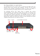
2.2 Rear Panel The rear panel of the 802.3at PoE+ Switch has an AC power socket (100 to 240V AC, 50-60Hz, 2.5/5A). 100-240V AC 50/60Hz, 2.5A Figure 2-4: GSD-1222VHP Switch Rear Panel 100~240V AC 50/60Hz, 5A max. Figure 2-5: GSW-1820VHP/GSW-2620VHP Switch Rear Panel AC Power Receptacle For compatibility with electrical outlet standard in most areas of the world, the 802.3at PoE+ Switch’s power supply automatically adjusts to line power in the range of 100-240V AC and 50/60Hz, 2.5/5A.
2.3 LCD Management The operation of the 5 buttons (Menu, Enter, Back, Up and Down) on the panel: Menu (5 sec) Switch Port Information 01 30.3W ---M 867M 08 ----W ---M ---M Up 02 ----W ---M ---M 09 -8.3W ---M -<1M 03 ----W ---M ---M 10 ----W ---M ---M Enter 04 15.4W -10M ---M 11 -OFF- ---M ---M 05 ----W ---M ---M 12 ----W ---M ---M 06 ----W ---M ---M 13 17.
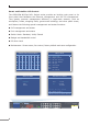
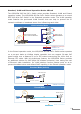
2.3.1 Switch Mode There are three modes -- “Standard”, “VLAN” and “Extend” – for selection. Model GSD-1222VHP Switch Mode GSW-1820VHP GSW-2620VHP Function Standard This mode makes the 802.3at PoE+ Switch operate as a general switch and (default) all PoE ports operate at 10/100/1000Mbps auto-negotiation. VLAN This mode makes the GSD-1222VHP operate as a VLAN isolation switch and 1. Port 1 to port 8 will isolate respectively. 2. Port 1 to port 8 can only communicate with port 9~12 (uplink port).
Standard Mode (default) > Standard PoE IP Camera VLAN Extend PoE Power GSW-1820VHP 100 meters (328 feet) 1000BASE-T UTP with PoE PoE VLAN Isolation Mode NVR PoE IP Camera PoE 1000 Standard Ports 17 and 18 for uplink Ports 1~16 Access Permitted > VLAN IP Camera Ports 1 to 16 Access Denied PoE Extend IP Camera GSW-1820VHP PC 1000BASE-SX/LX Fiber-optic 1000 1000BASE-T UTP 1000BASE-T UTP with PoE PoE Extend Mode Standard PoE IP Camera VLAN > Extend PoE Power GSW-1820VHP 250 meters (82
VLAN Isolation Feature The 802.3at PoE+ Switch has one feature called VLAN function. When switching the mode to the “VLAN” position, port 1 to port 8/16/24 wouldn’t able to communicate with each other. VLAN 1: P1 P17 P18 VLAN 2: P2 P17 P18 Standard > VLAN VLAN 16: P16 P17 P18 Extend Menu (5 sec) Switch Mode Options: GSW-1820VHP Up 2 4 6 8 10 12 14 16 1 3 5 7 9 11 13 15 Standard Enter > VLAN Extend Back 2 4 6 8 10 12 14 16 PoE Down 1 PWR 16-Port 10/100/1000T 802.
2.3.3 PSE Port Priority The Priority represents PoE ports priority. There are three levels of power priority named Low, High and Critical. The priority is used in case the total power consumption is over the total power budget. In this case the port with the lowest priority will be turned off, and offer power for the port of higher priority. The default port priority is “Low”. 2.3.4 PSE Port Enable Allows user to disable or enable per port PoE function. The default is “Enable”.
2.3.5 PD Type Changing the PoE power-up mode can let non-standard PDs pass the procedures of PoE power delivery process. This way, the switch can supply power to nonstandard PDs. The GSD/GSW 802.3at PoE+ Switch series can set the PoE powerup mode to be in Enhance mode, Standard mode or Legacy mode by the user interface.
2.3.6 Alive Check The GSD/GSW 802.3at PoE+ Switch series can be configured to monitor connected PD’s status in real time via traffic detection. Once there is no traffic at interval time, the GSD/GSW 802.3at PoE+ Switch series is going to restart PoE port power, and bring the PD back to work. It will greatly enhance the reliability and reduce administrator management burden. Object Description Port Select the port number to enable Alive Check.
The PD Alive Check is not a defining standard, so the PoE device on the market doesn’t report reboots done information to the PoE Switch. So user has to make sure how long it takes for the PD to finish booting, and then set the time value related column. The system is going to check the PD again according to the reboot time. If you cannot make sure the precise booting time, we suggest you set it longer.
2.3.8 Fan Control Fan control is to achieve the set power with intelligent operation. There are four levels of budget control, namely Always ON, 20% PB (default), 40% PB and 60% PB. 2.3.9 Screen Saver There are four levels of budget control, namely Always ON, 10min (default), 20min and 30min.
2.3.10 Language There are two languages, namely English and Chinese. 2.3.11 Default Setting Press “Yes” to reset to default. 2.3.12 System Show the system information.
3. Hardware Installation Start up Please refer to the following for your cabling: 10/100/1000BASE-T All 10/100/1000BASE-T ports come with Auto-Negotiation capability. They automatically support 1000BASE-T, 100BASE-TX and 10BASE-T networks. Users only need to plug a working network device into one of the 10/100/1000BASE-T ports, and then turn on the 802.3at PoE+ Switch.
3.1 Desktop Installation To install the 802.3at PoE+ Switch on desktop, simply follow the following steps: Step 1: Attach the rubber feet to the recessed areas on the bottom of the 802.3at PoE+ Ethernet Switch, as shown in Figure 3-1.
3.2 Rack Mounting To install the 802.3at PoE+ Switch in a 19-inch standard rack, follow the instructions described below. Step 1: Place your 802.3at PoE+ Switch on a hard flat surface, with the front panel positioned towards your front side. Step 2: Attach a rack-mount bracket to each side of the 802.3at PoE+ Switch with supplied screws attached to the package. Figure 3-2 shows how to attach brackets to one side of the 802.3at PoE+ Switch.
3.3 Installing the SFP Transceiver The sections describe how to insert an SFP transceiver into an SFP slot of the 802.3at PoE+ Switch. The SFP transceivers are hot-pluggable and hot-swappable. You can plug in and out the transceiver to/from any SFP port without having to power down the 802.3at PoE+ Switch, as the Figure 3-4 shows. 1 MGB-Series Module 2 LC Fiber Cable Figure 3-4: Plugging in the SFP Transceiver Approved PLANET SFP Transceivers PLANET 802.
Note It is recommended to use PLANET SFP on the 802.3at PoE+ Switch. If you insert an SFP transceiver that is not supported, the 802.3at PoE+ Switch will not recognize it. 1. Before we connect the 802.3at PoE+ Switch to the other network device, we have to make sure both sides of the SFP transceivers are with the same media type, for example, 1000BASE-SX to 1000BASE-SX; 1000BASE-LX to 1000BASELX. 2. Check whether the fiber-optic cable type matches with the SFP transceiver requirement.
Never pull out the module without lifting up the lever of the module and turning it to a horizontal position. Directly pulling out the module could damage the module and the SFP module slot of the 802.3at PoE+ Switch. Note 3.4 Product Applications Department/Workgroup PoE Switch: Providing 8/16/24 PoE in-line power interfaces, the 802.3at PoE+ Switch can easily build a power that centrally controls IP phone system, IP camera system and wireless AP group for enterprises.
3.5 Power over Ethernet Powered Devices 3~5 watts Voice over IP Phones As many as PoE VoIP phones, ATAs and other Ethernet/ non-Ethernet end-devices can be installed, but UPS is needed for uninterrupted power system and power control system. 6~12 watts Wireless LAN Access Points Access points can readily be installed in museums, sightseeing sites, airports, hotels, campuses, factories and warehouses.
4. Power over Ethernet Overview What is PoE? PoE is an abbreviation of Power over Ethernet. The PoE technology means a system safely transmits both power and data on Ethernet UTP cable. The IEEE standard for PoE technology requires Category 5 cable or higher for high power PoE levels, but can operate with Cat3 cable for low power levels.
intermediary device between a non-PoE capable switch and a PoE device, it is called a mid-span. An external PoE injector is a mid-span device. Powered Device A powered device (PD) is a device powered by a PSE and thus consumes energy. Examples include wireless access points, IP phones, and IP cameras. Many powered devices have an auxiliary power connector for an optional, external power supply.
The data pairs are used. Since Ethernet pairs are transformers coupled at each end, it is possible to apply DC power to the center tap of the isolated transformer without upsetting the data transfer. In this mode of operation, the pair on pins 3 and 6 and the pair on pins 1 and 2 can be of either polarity.
5. Troubleshooting This chapter contains information to help you solve issues. If the 802.3at PoE+ Switch is not functioning properly, make sure the 802.3at PoE+ Switch was set up according to instructions in this manual. The Link LED is not lit. Solution: Check the cable connection and also try to swap one new cable. 1000BASE-T port link LED is lit, but the traffic is irregular. Solution: Make sure the attached device is not set to full duplex.
Appendix A Networking Connection A.1 Switch's Data RJ45 Pin Assignments - 1000Mbps, 1000BASE-T PIN NO MDI MDI-X 1 BI_DA+ BI_DB+ 2 BI_DA- BI_DB- 3 BI_DB+ BI_DA+ 4 BI_DC+ BI_DD+ 5 BI_DC- BI_DD- 6 BI_DB- BI_DA- 7 BI_DD+ BI_DC+ 8 BI_DD- BI_DC- Implicit implementation of the crossover function within a twisted-pair cable, or at a wiring panel, while not expressly forbidden, is beyond the scope of this standard. A.
The standard cable, RJ45 pin assignment The standard RJ45 receptacle/connector There are 8 wires on a standard UTP/STP cable and each wire is color-coded.
EC Declaration of Conformity For the following equipment: *Type of Product : 8-Port 10/100/1000T 802.3at PoE + 2-Port 10/100/1000T + 2-Port 1000X SFP Ethernet Switch with PoE LCD Monitor *Model Number GSD-1222VHP : * Produced by: Manufacturer‘s Name : Planet Technology Corp. Manufacturer‘s Address : 10F., No.96, Minquan Rd., Xindian Dist.
EC Declaration of Conformity For the following equipment: *Type of Product : 16/24-Port 10/100/1000T 802.3at PoE + 2-Port Gigabit SFP Ethernet Switch with LCD PoE Monitor (300W) *Model Number GSW-1820VHP, GSW-2620VHP : * Produced by: Manufacturer‘s Name : Planet Technology Corp. Manufacturer‘s Address : 10F., No.96, Minquan Rd., Xindian Dist.