
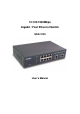
Gigabit / Fast Ethernet Switch User's Manual GSD-1020

- 2 -
2. HARDWARE DESCRIPTION
This section describes the hardware features of the Giga Switch. For easier management and control of the
switch, familiarize yourself with its display indicators, and ports. Front panel illustrations in this chapter display
the unit LED indicators. Before connecting any network device to the Switch, read this chapter carefully.
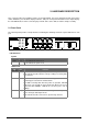
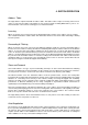
2.1 Front Panel
The unit front panel provides a simple interface monitoring the switching. It includes a power indicator for each
port.
Figure 1: GSD-1020 Switch front panel
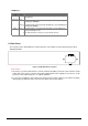
LED indicators:
System
100Base-TX
LED Color Function
PWR Green
Lit on: indicate the power is on.
Lit off: indicate the power is off.
LED Color Function
LNK / ACT Green
Lit: indicate the link through that port is successfully established.
Blink: indicate that the switch is actively sending or receiving data
over that port.
100 Green
Each RJ45 station port on the Switch is assigned one LED for
monitoring port "Good Link" and data traffic.
The LED is normally OFF. After the power on operation, LED will
light green color steadily to show "Good Link" when port is been
connected with 100Mbps. LED will be off when port is run at
10Mbps.
FDX Orange
Lit: indicate that the connection made through the corresponding
port is running in Full Duplex mode.
Blink: indicate that the connection is experiencing collisions