
User's Manual

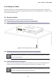
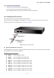

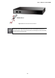


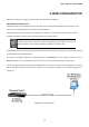
Table Of Contents
- 1. INTRODUCTION
- 2. INSTALLATION
- 3. SWITCH MANAGEMENT
- 4. WEB CONFIGURATION
- 4.1 Main Web Page
- 4.2 System
- 4.3 Port Management
- 4.4 Link Aggregation
- 4.5 VLAN
- 4.5.1 VLAN Overview
- 4.5.2 IEEE 802.1Q VLAN
- 4.5.3 Management VLAN
- 4.5.4 Create VLAN
- 4.5.5 Interface Settings
- 4.5.6 Port to VLAN
- 4.5.7 Port VLAN Membership
- 4.5.8 Protocol VLAN Group Setting
- 4.5.9 Protocol VLAN Port Setting
- 4.5.10 GVRP Setting
- 4.5.11 GVRP Port Setting
- 4.5.12 GVRP VLAN
- 4.5.13 GVRP Statistics
- 4.5.14 VLAN setting example:
- 4.6 Spanning Tree Protocol
- 4.7 Multicast
- 4.8 Quality of Service
- 4.9 Security
- 4.10 ACL
- 4.11 MAC Address Table
- 4.12 LLDP
- 4.13 Diagnostics
- 4.14 RMON
- 4.15 Maintenance
- 5. SWITCH OPERATION
- 6. TROUBLESHOOTING
- APPENDIX A
- GSD-1002M

User’s Manual of GSD-1002M
2.1.3 Switch Rear Panel
The rear panel of the Managed Switch indicates a DC inlet power socket. Figure 2-3 shows the rear panel of these Managed
Switches
Rear Panel
Figure 2-3 Rear panel of GSD-1002M
■ Gigabit TP Interface
10/100/1000Base-T Copper, RJ-45 Twist-Pair: Up to 100 meters.
■ DC Power Receptacle
For compatibility with electric service in most areas of the world, the Managed Switch’s power supply comes with a 12V DC
power adapter
Power Notice:
The device is a power-required device, which means it will not work till it is powered. If your networks
should be active all the time, please consider using UPS (Uninterrupted Power Supply) for your device.
It will prevent you from network data loss or network downtime.
Power Notice:
In some areas, installing a surge suppression device may also help to protect your Managed Switch
from being damaged by unregulated surge or current to the Managed Switch or the power adapter.
■ PoE-in (Port 8)
Supports 802.3af / at PoE 48~56V DC in-line power
21