
User's Manual
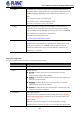


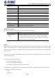


Table Of Contents
- 1. INTRODUCTION
- 2. INSTALLATION
- 3. SWITCH MANAGEMENT
- 4. WEB CONFIGURATION
- 4.1 Main Web Page
- 4.2 System
- 4.2.1 Management
- 4.2.1.1 System Information
- 4.2.1.2 IP Configuration
- 4.2.1.3 IP Status
- 4.2.1.4 Users Configuration
- 4.2.1.5 Privilege Levels
- 4.2.1.6 NTP Configuration
- 4.2.1.6.1 System Time Correction Manually
- 4.2.1.7 Time Configuration
- 4.2.1.8 UPnP
- 4.2.1.9 DHCP Relay
- 4.2.1.10 DHCP Relay Statistics
- 4.2.1.11 CPU Load
- 4.2.1.12 System Log
- 4.2.1.13 Detailed Log
- 4.2.1.14 Remote Syslog
- 4.2.1.15 SMTP Configuration
- 4.2.2 Simple Network Management Protocol
- 4.2.3 RMON
- 4.2.4 DHCP server
- 4.2.5 Remote Management
- 4.2.6 Power Management
- 4.2.1 Management
- 4.3 Switching
- 4.3.1 Port Management
- 4.3.2 Link Aggregation
- 4.3.3 VLAN
- 4.3.3.1 VLAN Overview
- 4.3.3.2 IEEE 802.1Q VLAN
- 4.3.3.3 VLAN Port Configuration
- 4.3.3.4 VLAN Membership Status
- 4.3.3.5 VLAN Port Status
- 4.3.3.6 Private VLAN
- 4.3.3.7 Port Isolation
- 4.3.3.8 VLAN setting example:
- 4.3.3.8.1 Two Separate 802.1Q VLANs
- 4.3.3.8.2 VLAN Trunking between two 802.1Q aware switches
- 4.3.3.8.3 Port Isolate
- 4.3.3.9 MAC-based VLAN
- 4.3.3.10 IP Subnet-based VLAN Membership Configuration
- 4.3.3.11 Protocol-based VLAN
- 4.3.3.12 Protocol-based VLAN Membership
- 4.3.4 Spanning Tree Protocol
- 4.3.5 Multicast
- 4.3.6 MLD Snooping
- 4.3.7 MVR (Multicast VLAN Registration)
- 4.3.8 LLDP
- 4.3.9 MAC Address Table
- 4.3.10 Loop Protection
- 4.3.11 UDLD
- 4.3.12 GVRP
- 4.3.13 Link OAM
- 4.4 Quality of Service
- 4.5 Security
- 4.6 Power over Ethernet
- 4.7 Ring
- 4.8 ONVIF
- 4.8 Maintenance
- 4.9 Routing
- 4.9.1 IP Configuration
- 4.9.2 IP Status
- 4.9.3 Routing Information Base
- 4.9.4 OSPF
- 4.9.4.1 Global Configuration
- 4.9.4.2 Network Area
- 4.9.4.3 Passive Interface
- 4.9.4.4 Stub Area
- 4.9.4.5 Area Authentication
- 4.9.4.6 Area Range
- 4.9.4.7 Interface Configuration
- 4.9.4.8 Virtual Link
- 4.9.4.9 Global Status
- 4.9.4.10 Area Status
- 4.9.4.11 Neighbor Status
- 4.9.4.12 Interface Status
- 4.9.4.13 Configuration Example of OSPFv4
- 5. SWITCH OPERATION
- 6. TROUBLESHOOTING
- APPENDIX A: Networking Connection
- APPENDIX B : GLOSSARY

User’s Manual of GS-6322 Managed Switch Series
212
TLVs and discarded CDP frames are not shown in the LLDP statistics.). CDP
TLVs are mapped onto LLDP neighbours' table as shown below.
CDP TLV "Device ID" is mapped to the LLDP "Chassis ID" field.
CDP TLV "Address" is mapped to the LLDP "Management Address" field. The
CDP address TLV can contain multiple addresses, but only the first address is
shown in the LLDP neighbours table.
CDP TLV "Port ID" is mapped to the LLDP "Port ID" field.
CDP TLV "Version and Platform" is mapped to the LLDP "System Description"
field.
Both the CDP and LLDP support "system capabilities", but the CDP capabilities
cover capabilities that are not part of the LLDP. These capabilities are shown as
"others" in the LLDP neighbours' table.
If all ports have CDP awareness disabled the switch forwards CDP frames
received from neighbour devices. If at least one port has CDP awareness
enabled all CDP frames are terminated by the switch.
Note: When CDP awareness on a port is disabled the CDP information isn't
removed immediately, but gets removed when the hold time is exceeded.
• Port Description
Optional TLV: When checked the "port description" is included in LLDP
information transmitted.
• System Name
Optional TLV: When checked the "system name" is included in LLDP information
transmitted.
• System Description
Optional TLV: When checked the "system description" is included in LLDP
information transmitted.
• System Capabilities
Optional TLV: When checked the "system capability" is included in LLDP
information transmitted.
• Management Address
Optional TLV: When checked the "management address" is included in LLDP
information transmitted.
Buttons
: Click to apply changes
: Click to undo any changes made locally and revert to previously saved values.
4.3.8.3 LLDP Neighbor
This page provides a status overview for all LLDP neighbors. The displayed table contains a row for each port on which an
LLDP neighbor is detected. The LLDP Neighbor Information screen in Figure 4-3-8-2 appears.