
User's Manual
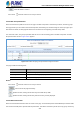

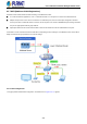


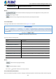

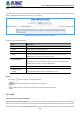

Table Of Contents
- 1. INTRODUCTION
- 2. INSTALLATION
- 3. SWITCH MANAGEMENT
- 4. WEB CONFIGURATION
- 4.1 Main Web Page
- 4.2 System
- 4.2.1 Management
- 4.2.1.1 System Information
- 4.2.1.2 IP Configuration
- 4.2.1.3 IP Status
- 4.2.1.4 Users Configuration
- 4.2.1.5 Privilege Levels
- 4.2.1.6 NTP Configuration
- 4.2.1.6.1 System Time Correction Manually
- 4.2.1.7 Time Configuration
- 4.2.1.8 UPnP
- 4.2.1.9 DHCP Relay
- 4.2.1.10 DHCP Relay Statistics
- 4.2.1.11 CPU Load
- 4.2.1.12 System Log
- 4.2.1.13 Detailed Log
- 4.2.1.14 Remote Syslog
- 4.2.1.15 SMTP Configuration
- 4.2.2 Simple Network Management Protocol
- 4.2.3 RMON
- 4.2.4 DHCP server
- 4.2.5 Remote Management
- 4.2.6 Power Management
- 4.2.1 Management
- 4.3 Switching
- 4.3.1 Port Management
- 4.3.2 Link Aggregation
- 4.3.3 VLAN
- 4.3.3.1 VLAN Overview
- 4.3.3.2 IEEE 802.1Q VLAN
- 4.3.3.3 VLAN Port Configuration
- 4.3.3.4 VLAN Membership Status
- 4.3.3.5 VLAN Port Status
- 4.3.3.6 Private VLAN
- 4.3.3.7 Port Isolation
- 4.3.3.8 VLAN setting example:
- 4.3.3.8.1 Two Separate 802.1Q VLANs
- 4.3.3.8.2 VLAN Trunking between two 802.1Q aware switches
- 4.3.3.8.3 Port Isolate
- 4.3.3.9 MAC-based VLAN
- 4.3.3.10 IP Subnet-based VLAN Membership Configuration
- 4.3.3.11 Protocol-based VLAN
- 4.3.3.12 Protocol-based VLAN Membership
- 4.3.4 Spanning Tree Protocol
- 4.3.5 Multicast
- 4.3.6 MLD Snooping
- 4.3.7 MVR (Multicast VLAN Registration)
- 4.3.8 LLDP
- 4.3.9 MAC Address Table
- 4.3.10 Loop Protection
- 4.3.11 UDLD
- 4.3.12 GVRP
- 4.3.13 Link OAM
- 4.4 Quality of Service
- 4.5 Security
- 4.6 Power over Ethernet
- 4.7 Ring
- 4.8 ONVIF
- 4.8 Maintenance
- 4.9 Routing
- 4.9.1 IP Configuration
- 4.9.2 IP Status
- 4.9.3 Routing Information Base
- 4.9.4 OSPF
- 4.9.4.1 Global Configuration
- 4.9.4.2 Network Area
- 4.9.4.3 Passive Interface
- 4.9.4.4 Stub Area
- 4.9.4.5 Area Authentication
- 4.9.4.6 Area Range
- 4.9.4.7 Interface Configuration
- 4.9.4.8 Virtual Link
- 4.9.4.9 Global Status
- 4.9.4.10 Area Status
- 4.9.4.11 Neighbor Status
- 4.9.4.12 Interface Status
- 4.9.4.13 Configuration Example of OSPFv4
- 5. SWITCH OPERATION
- 6. TROUBLESHOOTING
- APPENDIX A: Networking Connection
- APPENDIX B : GLOSSARY

User’s Manual of GS-6322 Managed Switch Series
209
Table.
The "Start from VLAN", and "Group Address" input fields allow the user to select the starting point in the MVR SFM Information
Table. The MVR SFM Information screen in Figure 4-3-7-4 appears.
Figure 4-3-7-4: MVR SFM Information Page Screenshot
The page includes the following fields:
Object Description
• VLAN ID
VLAN ID of the group.
• Group
Group address of the group displayed.
• Port
Switch port number.
• Mode
Indicates the filtering mode maintained per (VLAN ID, port number, Group
Address) basis. It can be either Include or Exclude.
• Source Address
IP Address of the source. Currently, system limits the total number of IP source
addresses for filtering to be 128. When there is no any source filtering address,
the text "None" is shown in the Source Address field.
• Type
Indicates the Type. It can be either Allow or Deny.
• Hardware Filter /
Switch
Indicates whether data plane destined to the specific group address from the
source IPv4/IPv6 address could be handled by chip or not.
Buttons
Auto-refresh : Automatic refresh occurs every 3 seconds.
: Refreshes the displayed table starting from the input fields.
: Updates the table starting from the first entry in the MVR SFM Information Table.
4.3.8 LLDP
4.3.8.1 Link Layer Discovery Protocol
Link Layer Discovery Protocol (LLDP) is used to discover basic information about neighboring devices on the local broadcast
domain. LLDP is a Layer 2 protocol that uses periodic broadcasts to advertise information about the sending device. Advertised
information is represented in Type Length Value (TLV) format according to the IEEE 802.1ab standard, and can include details