
User's Manual


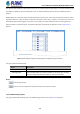


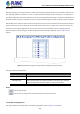
Table Of Contents
- 1. INTRODUCTION
- 2. INSTALLATION
- 3. SWITCH MANAGEMENT
- 4. WEB CONFIGURATION
- 4.1 Main Web Page
- 4.2 System
- 4.2.1 Management
- 4.2.1.1 System Information
- 4.2.1.2 IP Configuration
- 4.2.1.3 IP Status
- 4.2.1.4 Users Configuration
- 4.2.1.5 Privilege Levels
- 4.2.1.6 NTP Configuration
- 4.2.1.6.1 System Time Correction Manually
- 4.2.1.7 Time Configuration
- 4.2.1.8 UPnP
- 4.2.1.9 DHCP Relay
- 4.2.1.10 DHCP Relay Statistics
- 4.2.1.11 CPU Load
- 4.2.1.12 System Log
- 4.2.1.13 Detailed Log
- 4.2.1.14 Remote Syslog
- 4.2.1.15 SMTP Configuration
- 4.2.2 Simple Network Management Protocol
- 4.2.3 RMON
- 4.2.4 DHCP server
- 4.2.5 Remote Management
- 4.2.6 Power Management
- 4.2.1 Management
- 4.3 Switching
- 4.3.1 Port Management
- 4.3.2 Link Aggregation
- 4.3.3 VLAN
- 4.3.3.1 VLAN Overview
- 4.3.3.2 IEEE 802.1Q VLAN
- 4.3.3.3 VLAN Port Configuration
- 4.3.3.4 VLAN Membership Status
- 4.3.3.5 VLAN Port Status
- 4.3.3.6 Private VLAN
- 4.3.3.7 Port Isolation
- 4.3.3.8 VLAN setting example:
- 4.3.3.8.1 Two Separate 802.1Q VLANs
- 4.3.3.8.2 VLAN Trunking between two 802.1Q aware switches
- 4.3.3.8.3 Port Isolate
- 4.3.3.9 MAC-based VLAN
- 4.3.3.10 IP Subnet-based VLAN Membership Configuration
- 4.3.3.11 Protocol-based VLAN
- 4.3.3.12 Protocol-based VLAN Membership
- 4.3.4 Spanning Tree Protocol
- 4.3.5 Multicast
- 4.3.6 MLD Snooping
- 4.3.7 MVR (Multicast VLAN Registration)
- 4.3.8 LLDP
- 4.3.9 MAC Address Table
- 4.3.10 Loop Protection
- 4.3.11 UDLD
- 4.3.12 GVRP
- 4.3.13 Link OAM
- 4.4 Quality of Service
- 4.5 Security
- 4.6 Power over Ethernet
- 4.7 Ring
- 4.8 ONVIF
- 4.8 Maintenance
- 4.9 Routing
- 4.9.1 IP Configuration
- 4.9.2 IP Status
- 4.9.3 Routing Information Base
- 4.9.4 OSPF
- 4.9.4.1 Global Configuration
- 4.9.4.2 Network Area
- 4.9.4.3 Passive Interface
- 4.9.4.4 Stub Area
- 4.9.4.5 Area Authentication
- 4.9.4.6 Area Range
- 4.9.4.7 Interface Configuration
- 4.9.4.8 Virtual Link
- 4.9.4.9 Global Status
- 4.9.4.10 Area Status
- 4.9.4.11 Neighbor Status
- 4.9.4.12 Interface Status
- 4.9.4.13 Configuration Example of OSPFv4
- 5. SWITCH OPERATION
- 6. TROUBLESHOOTING
- APPENDIX A: Networking Connection
- APPENDIX B : GLOSSARY

User’s Manual of GS-6322 Managed Switch Series
200
port can join.
MLD filtering enables you to assign a profile to a switch port that specifies multicast groups that are permitted or denied on the
port. A MLD filter profile can contain one or more, or a range of multicast addresses; but only one profile can be assigned to a
port. When enabled, MLD join reports received on the port are checked against the filter profile. If a requested multicast group is
permitted, the MLD join report is forwarded as normal. If a requested multicast group is denied, the MLD join report is dropped.
MLD throttling sets a maximum number of multicast groups that a port can join at the same time. When the maximum number of
groups is reached on a port, the switch can take one of two actions; either “deny” or “replace”. If the action is set to deny, any
new MLD join reports will be dropped. If the action is set to replace, the switch randomly removes an existing group and
replaces it with the new multicast group. The MLD Snooping Port Group Filtering Configuration screen in Figure 4-3-6-3
appears.
Figure 4-3-6-3: MLD Snooping Port Group Filtering Configuration Page Screenshot
The page includes the following fields:
Object Description
• Port
The logical port for the settings.
• Filtering Group
Select the IPMC Profile as the filtering condition for the specific port. Summary
about the designated profile will be shown by clicking the view button.
Buttons
: Click to apply changes
: Click to undo any changes made locally and revert to previously saved values.
4.3.6.4 MLD Snooping Status
This page provides MLD Snooping status. The IGMP Snooping Status screen in Figure 4-3-6-4 appears.