
User's Manual


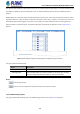


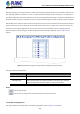
Table Of Contents
- 1. INTRODUCTION
- 2. INSTALLATION
- 3. SWITCH MANAGEMENT
- 4. WEB CONFIGURATION
- 4.1 Main Web Page
- 4.2 System
- 4.2.1 Management
- 4.2.1.1 System Information
- 4.2.1.2 IP Configuration
- 4.2.1.3 IP Status
- 4.2.1.4 Users Configuration
- 4.2.1.5 Privilege Levels
- 4.2.1.6 NTP Configuration
- 4.2.1.6.1 System Time Correction Manually
- 4.2.1.7 Time Configuration
- 4.2.1.8 UPnP
- 4.2.1.9 DHCP Relay
- 4.2.1.10 DHCP Relay Statistics
- 4.2.1.11 CPU Load
- 4.2.1.12 System Log
- 4.2.1.13 Detailed Log
- 4.2.1.14 Remote Syslog
- 4.2.1.15 SMTP Configuration
- 4.2.2 Simple Network Management Protocol
- 4.2.3 RMON
- 4.2.4 DHCP server
- 4.2.5 Remote Management
- 4.2.6 Power Management
- 4.2.1 Management
- 4.3 Switching
- 4.3.1 Port Management
- 4.3.2 Link Aggregation
- 4.3.3 VLAN
- 4.3.3.1 VLAN Overview
- 4.3.3.2 IEEE 802.1Q VLAN
- 4.3.3.3 VLAN Port Configuration
- 4.3.3.4 VLAN Membership Status
- 4.3.3.5 VLAN Port Status
- 4.3.3.6 Private VLAN
- 4.3.3.7 Port Isolation
- 4.3.3.8 VLAN setting example:
- 4.3.3.8.1 Two Separate 802.1Q VLANs
- 4.3.3.8.2 VLAN Trunking between two 802.1Q aware switches
- 4.3.3.8.3 Port Isolate
- 4.3.3.9 MAC-based VLAN
- 4.3.3.10 IP Subnet-based VLAN Membership Configuration
- 4.3.3.11 Protocol-based VLAN
- 4.3.3.12 Protocol-based VLAN Membership
- 4.3.4 Spanning Tree Protocol
- 4.3.5 Multicast
- 4.3.6 MLD Snooping
- 4.3.7 MVR (Multicast VLAN Registration)
- 4.3.8 LLDP
- 4.3.9 MAC Address Table
- 4.3.10 Loop Protection
- 4.3.11 UDLD
- 4.3.12 GVRP
- 4.3.13 Link OAM
- 4.4 Quality of Service
- 4.5 Security
- 4.6 Power over Ethernet
- 4.7 Ring
- 4.8 ONVIF
- 4.8 Maintenance
- 4.9 Routing
- 4.9.1 IP Configuration
- 4.9.2 IP Status
- 4.9.3 Routing Information Base
- 4.9.4 OSPF
- 4.9.4.1 Global Configuration
- 4.9.4.2 Network Area
- 4.9.4.3 Passive Interface
- 4.9.4.4 Stub Area
- 4.9.4.5 Area Authentication
- 4.9.4.6 Area Range
- 4.9.4.7 Interface Configuration
- 4.9.4.8 Virtual Link
- 4.9.4.9 Global Status
- 4.9.4.10 Area Status
- 4.9.4.11 Neighbor Status
- 4.9.4.12 Interface Status
- 4.9.4.13 Configuration Example of OSPFv4
- 5. SWITCH OPERATION
- 6. TROUBLESHOOTING
- APPENDIX A: Networking Connection
- APPENDIX B : GLOSSARY

User’s Manual of GS-6322 Managed Switch Series
191
The Switch forwards IGMP join or leave packets to an IGMP router port.
Auto:
Select “Auto” to have theGS-6322 Series PoE Switch automatically
uses the port as IGMP Router port if the port receives IGMP query
packets.
Fix:
TheGS-6322 Series PoE Switch always uses the specified port as an
IGMP Router port. Use this mode when you connect an IGMP
multicast server or IP camera which applied with multicast protocol to
the port.
None:
TheGS-6322 Series PoE Switch will not use the specified port as an
IGMP Router port. TheGS-6322 Series PoE Switch will not keep any
record of an IGMP router being connected to this port. Use this mode
when you connect other IGMP multicast servers directly on the
non-querierGS-6322 Series PoE Switch and don’t want the multicast
stream to be flooded by uplinking switch through the port that is
connected to the IGMP querier.
• Fast Leave
Enable the fast leave on the port.
• Throtting
Enable to limit the number of multicast groups to which a switch port can belong.
Buttons
: Click to apply changes
: Click to undo any changes made locally and revert to previously saved values.
4.3.5.5 IGMP Snooping VLAN Configuration
Each page shows up to 99 entries from the VLAN table, default being 20, selected through the "entries per page" input field.
When first visited, the web page will show the first 20 entries from the beginning of the VLAN Table. The first displayed will be
the one with the lowest VLAN ID found in the VLAN Table.
The "VLAN" input fields allow the user to select the starting point in the VLAN Table. The IGMP Snooping VLAN Configuration
screen in Figure 4-3-5-8 appears.