
User's Manual


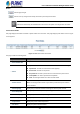


Table Of Contents
- 1. INTRODUCTION
- 2. INSTALLATION
- 3. SWITCH MANAGEMENT
- 4. WEB CONFIGURATION
- 4.1 Main Web Page
- 4.2 System
- 4.2.1 Management
- 4.2.1.1 System Information
- 4.2.1.2 IP Configuration
- 4.2.1.3 IP Status
- 4.2.1.4 Users Configuration
- 4.2.1.5 Privilege Levels
- 4.2.1.6 NTP Configuration
- 4.2.1.6.1 System Time Correction Manually
- 4.2.1.7 Time Configuration
- 4.2.1.8 UPnP
- 4.2.1.9 DHCP Relay
- 4.2.1.10 DHCP Relay Statistics
- 4.2.1.11 CPU Load
- 4.2.1.12 System Log
- 4.2.1.13 Detailed Log
- 4.2.1.14 Remote Syslog
- 4.2.1.15 SMTP Configuration
- 4.2.2 Simple Network Management Protocol
- 4.2.3 RMON
- 4.2.4 DHCP server
- 4.2.5 Remote Management
- 4.2.6 Power Management
- 4.2.1 Management
- 4.3 Switching
- 4.3.1 Port Management
- 4.3.2 Link Aggregation
- 4.3.3 VLAN
- 4.3.3.1 VLAN Overview
- 4.3.3.2 IEEE 802.1Q VLAN
- 4.3.3.3 VLAN Port Configuration
- 4.3.3.4 VLAN Membership Status
- 4.3.3.5 VLAN Port Status
- 4.3.3.6 Private VLAN
- 4.3.3.7 Port Isolation
- 4.3.3.8 VLAN setting example:
- 4.3.3.8.1 Two Separate 802.1Q VLANs
- 4.3.3.8.2 VLAN Trunking between two 802.1Q aware switches
- 4.3.3.8.3 Port Isolate
- 4.3.3.9 MAC-based VLAN
- 4.3.3.10 IP Subnet-based VLAN Membership Configuration
- 4.3.3.11 Protocol-based VLAN
- 4.3.3.12 Protocol-based VLAN Membership
- 4.3.4 Spanning Tree Protocol
- 4.3.5 Multicast
- 4.3.6 MLD Snooping
- 4.3.7 MVR (Multicast VLAN Registration)
- 4.3.8 LLDP
- 4.3.9 MAC Address Table
- 4.3.10 Loop Protection
- 4.3.11 UDLD
- 4.3.12 GVRP
- 4.3.13 Link OAM
- 4.4 Quality of Service
- 4.5 Security
- 4.6 Power over Ethernet
- 4.7 Ring
- 4.8 ONVIF
- 4.8 Maintenance
- 4.9 Routing
- 4.9.1 IP Configuration
- 4.9.2 IP Status
- 4.9.3 Routing Information Base
- 4.9.4 OSPF
- 4.9.4.1 Global Configuration
- 4.9.4.2 Network Area
- 4.9.4.3 Passive Interface
- 4.9.4.4 Stub Area
- 4.9.4.5 Area Authentication
- 4.9.4.6 Area Range
- 4.9.4.7 Interface Configuration
- 4.9.4.8 Virtual Link
- 4.9.4.9 Global Status
- 4.9.4.10 Area Status
- 4.9.4.11 Neighbor Status
- 4.9.4.12 Interface Status
- 4.9.4.13 Configuration Example of OSPFv4
- 5. SWITCH OPERATION
- 6. TROUBLESHOOTING
- APPENDIX A: Networking Connection
- APPENDIX B : GLOSSARY

User’s Manual of GS-6322 Managed Switch Series
115
Buttons
: Click to apply changes
: Click to undo any changes made locally and revert to previously saved values.
If the RPS mode is slected, the power redundancy features is enabled and causing the total available
power that is delivered by all available PSUs to be less than the power that a single PSU can deliver.
4.2.6.2 Power Status
This page displays information and status of power module slot 1 and slot 2. This page displays power status screen in Figure
4-2-6-2 appears.
Figure 4-2-6-2: Power Status Screenshot
The page includes the following fields:
Object Description
• Power Module Slot
The power module slot number.
• Status
Displays the PSU status of Slot 1 and Slot 2, which can be one of the following:
Operational: The PSU is connected and works properly.
Not Present: The PSU is not present.
Not powered: The PSU is present but not connected to the power source.
Incompatible: The PSU is present but incompatibld.
Fault: The Managed Switch can’t detect the PSU status
• Module Number
The modle number of power module.
Note: The Managed Switch allows only PLANET proved CRPS power modules
can be installed.
• PoE Budget(W)
Displays the pre-defined available PoE budget of detected power module.
• Power Budget(W)
Displays the power consumption of power supply
• PSU DC Output(V)
Displays the power module output voltage.
• PSU AC Input(V)
Displays the power module input voltage.
• Temperatures
Displays the power module temperature.
• Fan Status
Display the power module fan status.