
User's Manual


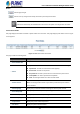


Table Of Contents
- 1. INTRODUCTION
- 2. INSTALLATION
- 3. SWITCH MANAGEMENT
- 4. WEB CONFIGURATION
- 4.1 Main Web Page
- 4.2 System
- 4.2.1 Management
- 4.2.1.1 System Information
- 4.2.1.2 IP Configuration
- 4.2.1.3 IP Status
- 4.2.1.4 Users Configuration
- 4.2.1.5 Privilege Levels
- 4.2.1.6 NTP Configuration
- 4.2.1.6.1 System Time Correction Manually
- 4.2.1.7 Time Configuration
- 4.2.1.8 UPnP
- 4.2.1.9 DHCP Relay
- 4.2.1.10 DHCP Relay Statistics
- 4.2.1.11 CPU Load
- 4.2.1.12 System Log
- 4.2.1.13 Detailed Log
- 4.2.1.14 Remote Syslog
- 4.2.1.15 SMTP Configuration
- 4.2.2 Simple Network Management Protocol
- 4.2.3 RMON
- 4.2.4 DHCP server
- 4.2.5 Remote Management
- 4.2.6 Power Management
- 4.2.1 Management
- 4.3 Switching
- 4.3.1 Port Management
- 4.3.2 Link Aggregation
- 4.3.3 VLAN
- 4.3.3.1 VLAN Overview
- 4.3.3.2 IEEE 802.1Q VLAN
- 4.3.3.3 VLAN Port Configuration
- 4.3.3.4 VLAN Membership Status
- 4.3.3.5 VLAN Port Status
- 4.3.3.6 Private VLAN
- 4.3.3.7 Port Isolation
- 4.3.3.8 VLAN setting example:
- 4.3.3.8.1 Two Separate 802.1Q VLANs
- 4.3.3.8.2 VLAN Trunking between two 802.1Q aware switches
- 4.3.3.8.3 Port Isolate
- 4.3.3.9 MAC-based VLAN
- 4.3.3.10 IP Subnet-based VLAN Membership Configuration
- 4.3.3.11 Protocol-based VLAN
- 4.3.3.12 Protocol-based VLAN Membership
- 4.3.4 Spanning Tree Protocol
- 4.3.5 Multicast
- 4.3.6 MLD Snooping
- 4.3.7 MVR (Multicast VLAN Registration)
- 4.3.8 LLDP
- 4.3.9 MAC Address Table
- 4.3.10 Loop Protection
- 4.3.11 UDLD
- 4.3.12 GVRP
- 4.3.13 Link OAM
- 4.4 Quality of Service
- 4.5 Security
- 4.6 Power over Ethernet
- 4.7 Ring
- 4.8 ONVIF
- 4.8 Maintenance
- 4.9 Routing
- 4.9.1 IP Configuration
- 4.9.2 IP Status
- 4.9.3 Routing Information Base
- 4.9.4 OSPF
- 4.9.4.1 Global Configuration
- 4.9.4.2 Network Area
- 4.9.4.3 Passive Interface
- 4.9.4.4 Stub Area
- 4.9.4.5 Area Authentication
- 4.9.4.6 Area Range
- 4.9.4.7 Interface Configuration
- 4.9.4.8 Virtual Link
- 4.9.4.9 Global Status
- 4.9.4.10 Area Status
- 4.9.4.11 Neighbor Status
- 4.9.4.12 Interface Status
- 4.9.4.13 Configuration Example of OSPFv4
- 5. SWITCH OPERATION
- 6. TROUBLESHOOTING
- APPENDIX A: Networking Connection
- APPENDIX B : GLOSSARY

User’s Manual of GS-6322 Managed Switch Series
114
Incompatible: The PSU is present but incompatible for GS-6322-24P4X.
With incompatible PSU, it only allows system is running without PoE output.
Fault: The Managed Switch can’t detect the PSU status.
• RPS mode (1+1) Active
Displays whether the RPS(1+1) power redundancy feature is enabled and works
properly. The possible values are one of the following:
Yes: The power module is operating with RPS mode and Number of PSU is 2
No:
(1) The power module is operating with EPS mode
(2) The power module is operating with RPS mode but Number of PSU is 1
(3) The power module is operating with RPS mode and Number of PSU is 2
but one of the Power Status is Fault
• Total Available Power
(W)
The total available power for the Managed Switch in watts.
• Total Available PoE
Budget (W)
According to Power Module operation mode, PSU status and Managed Switch
auto detected model of PSU module. The Managed Switch pre-defined total
available PoE budget as ollowing tables.
Input Power: 110V
Slot2
Slot1
-
920
Power
1200
Power
2000
Power
920
Power
RPS (Watt) 720 720 720 720
EPS (Watt) 720 1640 1720 1720
1200
Power
RPS (Watt) 800 720 800 800
EPS (Watt) 800 1720 1800 1800
2000
Power
RPS (Watt) 800 720 800 800
EPS (Watt) 800 1720 1800 1800
Input Power: 220V
Slot2
Slot1
-
920
Power
1200
Power
2000
Power
920
Power
RPS (Watt) 720 720 720 720
EPS (Watt) 720 1640 1920 2280
1200
Power
RPS (Watt) 1000 720 1000 1000
EPS (Watt) 1000 1920 2200 2280
2000
Power
RPS (Watt) 1600 720 1000 1800
EPS (Watt) 1600 2280 2280 2280