
User's Manual


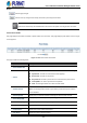


Table Of Contents
- 1. INTRODUCTION
- 2. INSTALLATION
- 3. SWITCH MANAGEMENT
- 4. WEB CONFIGURATION
- 4.1 Main Web Page
- 4.2 System
- 4.2.1 Management
- 4.2.1.1 System Information
- 4.2.1.2 IP Configuration
- 4.2.1.3 IP Status
- 4.2.1.4 Users Configuration
- 4.2.1.5 Privilege Levels
- 4.2.1.6 NTP Configuration
- 4.2.1.6.1 System Time Correction Manually
- 4.2.1.7 Time Configuration
- 4.2.1.8 UPnP
- 4.2.1.9 DHCP Relay
- 4.2.1.10 DHCP Relay Statistics
- 4.2.1.11 CPU Load
- 4.2.1.12 System Log
- 4.2.1.13 Detailed Log
- 4.2.1.14 Remote Syslog
- 4.2.1.15 SMTP Configuration
- 4.2.2 Simple Network Management Protocol
- 4.2.3 RMON
- 4.2.4 DHCP server
- 4.2.5 Remote Management
- 4.2.6 Power Management
- 4.2.1 Management
- 4.3 Switching
- 4.3.1 Port Management
- 4.3.2 Link Aggregation
- 4.3.3 VLAN
- 4.3.3.1 VLAN Overview
- 4.3.3.2 IEEE 802.1Q VLAN
- 4.3.3.3 VLAN Port Configuration
- 4.3.3.4 VLAN Membership Status
- 4.3.3.5 VLAN Port Status
- 4.3.3.6 Private VLAN
- 4.3.3.7 Port Isolation
- 4.3.3.8 VLAN setting example:
- 4.3.3.8.1 Two Separate 802.1Q VLANs
- 4.3.3.8.2 VLAN Trunking between two 802.1Q aware switches
- 4.3.3.8.3 Port Isolate
- 4.3.3.9 MAC-based VLAN
- 4.3.3.10 IP Subnet-based VLAN Membership Configuration
- 4.3.3.11 Protocol-based VLAN
- 4.3.3.12 Protocol-based VLAN Membership
- 4.3.4 Spanning Tree Protocol
- 4.3.5 Multicast
- 4.3.6 MLD Snooping
- 4.3.7 MVR (Multicast VLAN Registration)
- 4.3.8 LLDP
- 4.3.9 MAC Address Table
- 4.3.10 Loop Protection
- 4.3.11 UDLD
- 4.3.12 GVRP
- 4.3.13 Link OAM
- 4.4 Quality of Service
- 4.5 Security
- 4.6 Power over Ethernet
- 4.7 Ring
- 4.8 ONVIF
- 4.8 Maintenance
- 4.9 Routing
- 4.9.1 IP Configuration
- 4.9.2 IP Status
- 4.9.3 Routing Information Base
- 4.9.4 OSPF
- 4.9.4.1 Global Configuration
- 4.9.4.2 Network Area
- 4.9.4.3 Passive Interface
- 4.9.4.4 Stub Area
- 4.9.4.5 Area Authentication
- 4.9.4.6 Area Range
- 4.9.4.7 Interface Configuration
- 4.9.4.8 Virtual Link
- 4.9.4.9 Global Status
- 4.9.4.10 Area Status
- 4.9.4.11 Neighbor Status
- 4.9.4.12 Interface Status
- 4.9.4.13 Configuration Example of OSPFv4
- 5. SWITCH OPERATION
- 6. TROUBLESHOOTING
- APPENDIX A: Networking Connection
- APPENDIX B : GLOSSARY

User’s Manual of GS-6322 Managed Switch Series
112
4.2.6 Power Management
The GS-6322-24P4X is designed with two extractive modular power supply slots to support Redundant Power Supply(RPS)
mode or Extended Power Supply(EPS) mode via software setting to handle the demands of power redundancy or additional
power to PoE++ ports as needed.
RPS (1+1) mode: Where critical services are supported by PoE application, the secondary PSU is needed to provide
backup power in the event of a power outage. When two PSUs are installed, the power budget is the same as that of one
PSU.
EPS (2+0) mode: Where more PoE budget is required to support complete application, the secondary PSU can provide
additional PoE power. The two PSUs combined are able to provide a maximum of total PoE power.
Users can choose one or dual power supplies with the initial installation.
PSU Module
Operation mode
PoE Budget with
One 1200W PSU
PoE Budget with
Two 1200W PSUs
Power
Redundancy
RPS mode (1+1)
1000W 1000W Yes
EPS mode (2+0)
1000W 2200W --
Example on power supply: PWR-CRPS1200
The factory default power configuration are shown as follows.
Default Power Module Operation Mode: EPS