
Installation Guide

5
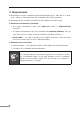
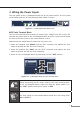
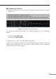
3. Wiring the Power Inputs
The rear panel of the L3 Managed Switch has an AC power socket, one DC power
on/oswitchandoneDCinletterminalblockwithin2screws.
49
10G/1G
50
10G/1G
51
10G/1G
52
10G/1G
ACT10G
ACT1G
V+
DC Input Range
36-60V
, 2A max.
ON
OFF
DC POWER
50/60Hz
Ensure the power switch
in the “OFF” position
before connect the DC wire.
CAUTION
100-240V , 1.2A max.
Figure 3-1: L3 Managed Switch Rear Panel
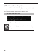
DC Inlet Terminal Block
The DC inlet terminal block accepts DC power input voltage from 36V to 60V DC.
Connectthepowercabletothe L3ManagedSwitchattheDCinputterminal block;
the size of the two screws in the terminal block is M3.5.
Please follow the steps below to insert the DC power wire.
1.Insert the negative wire (Black) into the “V-” connector and tighten the wire-
clamp to prevent the DC wire from loosening.
2.Insert the positive wire (Red) into the “V+” connector and tighten the wire-
clamp to prevent the DC wire from loosening.
3.PowerontheL3ManagedSwitchbyswitchingittothe“ON” position.
V+
DC Input Range
36-60V
, 2A max.
ON
OFF
DC POWER
Ensure the power switch
in the “OFF” position
before connect the DC wire.
CAUTION
Figure 3-2: L3 Managed Switch DC Inlet Terminal Block
Warning
Before connecting the DC power cable to the input terminal block
of the L3 Managed Switch, make sure that the power switch is in
the “OFF”positionandtheDCpowerisOFF.
Note
The wire gauge for the terminal block should be in the range from
12 to 24AWG.