
User's Manual
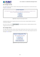

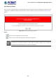
Table Of Contents
- 1. INTRODUCTION
- 2. INSTALLATION
- 3. SWITCH MANAGEMENT
- 4. WEB CONFIGURATION
- 4.1 Main Web Page
- 4.2 System
- 4.2.1 Management
- 4.2.1.1 System Information
- 4.2.1.2 IP Configuration
- 4.2.1.3 IP Status
- 4.2.1.4 ARP Configuration
- 4.2.1.5 Users Configuration
- 4.2.1.6 Privilege Levels
- 4.2.1.7 NTP Configuration
- 4.2.1.7.1 System Time Correction Manually
- 4.2.1.8 Time Configuration
- 4.2.1.9 UPnP
- 4.2.1.10 DHCP Relay
- 4.2.1.11 DHCP Relay Statistics
- 4.2.1.12 CPU Load
- 4.2.1.13 System Log
- 4.2.1.14 Detailed Log
- 4.2.1.15 Remote Syslog
- 4.2.1.16 SMTP Configuration
- 4.2.2 Simple Network Management Protocol
- 4.2.3 RMON
- 4.2.4 DHCP server
- 4.2.5 Remote Management
- 4.2.1 Management
- 4.3 Switching
- 4.3.1 Port Management
- 4.3.2 Link Aggregation
- 4.3.3 VLAN
- 4.3.3.1 VLAN Overview
- 4.3.3.2 IEEE 802.1Q VLAN
- 4.3.3.3 VLAN Port Configuration
- 4.3.3.4 VLAN Membership Status
- 4.3.3.5 VLAN Port Status
- 4.3.3.6 Private VLAN
- 4.3.3.7 Port Isolation
- 4.3.3.8 VLAN setting example:
- 4.3.3.8.1 Two Separate 802.1Q VLANs
- 4.3.3.8.2 VLAN Trunking between two 802.1Q aware switches
- 4.3.3.8.3 Port Isolate
- 4.3.3.9 MAC-based VLAN
- 4.3.3.10 IP Subnet-based VLAN
- 4.3.3.11 Protocol-based VLAN
- 4.3.3.12 Protocol-based VLAN Membership
- 4.3.4 VLAN Translation
- 4.3.5 Spanning Tree Protocol
- 4.3.6 Multicast
- 4.3.7 MLD Snooping
- 4.3.8 MVR (Multicast VLAN Registration)
- 4.3.9 LLDP
- 4.3.10 MAC Address Table
- 4.3.11 Loop Protection
- 4.3.12 UDLD
- 4.3.13 GVRP
- 4.4 Quality of Service
- 4.5 Security
- 4.6 Power over Ethernet
- 4.7 ONVIF
- 4.8 Maintenance
- 4.8.1 Web Firmware Upgrade
- 4.8.2 Save Startup Config
- 4.8.3 Configuration Download
- 4.8.4 Configuration Upload
- 4.8.5 Configure Activate
- 4.8.6 Configure Delete
- 4.8.7 Image Select
- 4.8.8 Factory Default
- 4.8.9 System Reboot
- 4.8.10 Ping
- 4.8.11 IPv6 Ping
- 4.8.12 Remote IP Ping
- 4.8.13 Cable Diagnostics
- 4.8.14 Traceroute (IPv4)
- 4.8.15 Traceroute (IPv6)
- 5. COMMAND LINE MODE
- 6. SWITCH OPERATION
- 7. TROUBLESHOOTING
- APPENDIX A: Networking Connection
- APPENDIX B : GLOSSARY

User’s Manual of GS-5220-8P2T2S Managed Switch
344
4.8.8 Factory Default
You can reset the configuration of the L2+ Managed PoE+ Switch on this page. Only the IP configuration is retained. The new
configuration is available immediately, which means that no restart is necessary. The Factory Default screen in Figure 4-8-8
appears.
Figure 4-8-8: Factory Default Page Screenshot
Buttons
: Click to reset the configuration to Factory Defaults.
: Click to return to the Port State page without resetting the configuration.
To reset the L2+ Managed PoE+ Switch
to the Factory default setting, you can also press the hardware
reset button at the front panel about 10 seconds. After the device is rebooted, you can login the
management Web interface within the same subnet of 192.168.0.xx.