
User's Manual
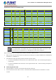
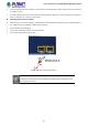


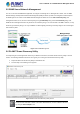
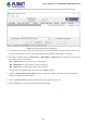
Table Of Contents
- 1. INTRODUCTION
- 2. INSTALLATION
- 3. SWITCH MANAGEMENT
- 4. WEB CONFIGURATION
- 4.1 Main Web Page
- 4.2 System
- 4.2.1 Management
- 4.2.1.1 System Information
- 4.2.1.2 IP Configuration
- 4.2.1.3 IP Status
- 4.2.1.4 ARP Configuration
- 4.2.1.5 Users Configuration
- 4.2.1.6 Privilege Levels
- 4.2.1.7 NTP Configuration
- 4.2.1.7.1 System Time Correction Manually
- 4.2.1.8 Time Configuration
- 4.2.1.9 UPnP
- 4.2.1.10 DHCP Relay
- 4.2.1.11 DHCP Relay Statistics
- 4.2.1.12 CPU Load
- 4.2.1.13 System Log
- 4.2.1.14 Detailed Log
- 4.2.1.15 Remote Syslog
- 4.2.1.16 SMTP Configuration
- 4.2.2 Simple Network Management Protocol
- 4.2.3 RMON
- 4.2.4 DHCP server
- 4.2.5 Remote Management
- 4.2.1 Management
- 4.3 Switching
- 4.3.1 Port Management
- 4.3.2 Link Aggregation
- 4.3.3 VLAN
- 4.3.3.1 VLAN Overview
- 4.3.3.2 IEEE 802.1Q VLAN
- 4.3.3.3 VLAN Port Configuration
- 4.3.3.4 VLAN Membership Status
- 4.3.3.5 VLAN Port Status
- 4.3.3.6 Private VLAN
- 4.3.3.7 Port Isolation
- 4.3.3.8 VLAN setting example:
- 4.3.3.8.1 Two Separate 802.1Q VLANs
- 4.3.3.8.2 VLAN Trunking between two 802.1Q aware switches
- 4.3.3.8.3 Port Isolate
- 4.3.3.9 MAC-based VLAN
- 4.3.3.10 IP Subnet-based VLAN
- 4.3.3.11 Protocol-based VLAN
- 4.3.3.12 Protocol-based VLAN Membership
- 4.3.4 VLAN Translation
- 4.3.5 Spanning Tree Protocol
- 4.3.6 Multicast
- 4.3.7 MLD Snooping
- 4.3.8 MVR (Multicast VLAN Registration)
- 4.3.9 LLDP
- 4.3.10 MAC Address Table
- 4.3.11 Loop Protection
- 4.3.12 UDLD
- 4.3.13 GVRP
- 4.4 Quality of Service
- 4.5 Security
- 4.6 Power over Ethernet
- 4.7 ONVIF
- 4.8 Maintenance
- 4.8.1 Web Firmware Upgrade
- 4.8.2 Save Startup Config
- 4.8.3 Configuration Download
- 4.8.4 Configuration Upload
- 4.8.5 Configure Activate
- 4.8.6 Configure Delete
- 4.8.7 Image Select
- 4.8.8 Factory Default
- 4.8.9 System Reboot
- 4.8.10 Ping
- 4.8.11 IPv6 Ping
- 4.8.12 Remote IP Ping
- 4.8.13 Cable Diagnostics
- 4.8.14 Traceroute (IPv4)
- 4.8.15 Traceroute (IPv6)
- 5. COMMAND LINE MODE
- 6. SWITCH OPERATION
- 7. TROUBLESHOOTING
- APPENDIX A: Networking Connection
- APPENDIX B : GLOSSARY

User’s Manual of GS-5220-8P2T2S Managed Switch
31
Gigabit Ethernet Transceiver (1000BASE-X SFP)
Model DDM
Speed
(Mbps)
Connector
Interface
Fiber Mode Distance Wavelength (nm) Operating Temp.
MGB-GT -- 1000 Copper -- 100m -- 0 ~ 60 degrees C
MGB-SX(V2) YES 1000 LC Multi Mode 550m 850nm 0 ~ 60 degrees C
MGB-SX2(V2) YES 1000 LC Multi Mode 2km 1310nm 0 ~ 60 degrees C
MGB-LX(V2) YES 1000 LC Single Mode 20km 1310nm 0 ~ 60 degrees C
MGB-L40 YES 1000 LC Single Mode 40km 1310nm 0 ~ 60 degrees C
MGB-L80 YES 1000 LC Single Mode 80km 1550nm 0 ~ 60 degrees C
MGB-L120(V2) YES 1000 LC Single Mode 120km 1550nm 0 ~ 60 degrees C
Gigabit Ethernet Transceiver (1000BASE-BX, Single Fiber Bi-directional SFP)
Model DDM
Speed
(Mbps)
Connector
Interface
Fiber Mode Distance
Wavelength
(TX)
Wavelength
(RX)
Operating Temp.
MGB-LA10(V2)
MGB-LB10(V2)
YES
1000 WDM(LC) Single Mode 10km 1310nm 1550nm 0 ~ 60 degrees C
1000 WDM(LC) Single Mode 10km 1550nm 1310nm 0 ~ 60 degrees C
MGB-LA20(V2)
MGB-LB20(V2)
YES
1000 WDM(LC) Single Mode 20km 1310nm 1550nm 0 ~ 60 degrees C
1000 WDM(LC) Single Mode 20km 1550nm 1310nm 0 ~ 60 degrees C
MGB-LA40(V2)
MGB-LB40(V2)
YES
1000 WDM(LC) Single Mode 40km 1310nm 1550nm 0 ~ 60 degrees C
1000 WDM(LC) Single Mode 40km 1550nm 1310nm 0 ~ 60 degrees C
MGB-LA80
MGB-LB80
YES
1000 WDM(LC) Single Mode 80km 1490nm 1550nm 0 ~ 60 degrees C
1000 WDM(LC) Single Mode 80km 1550nm 1490nm 0 ~ 60 degrees C
It is recommended to use PLANET SFP on the L2+ Managed PoE+ Switch. If you insert an SFP
transceiver that is not supported, the L2+ Managed PoE+ Switch will not recognize it.
Before connecting the other L2+ Managed PoE+ Switches, workstation or Media Converter.
1. Make sure both sides of the SFP transceiver are with the same media type, for example, 1000BASE-SX to 1000BASE-SX,
1000BASE-LX to 1000BASE-LX.
2. Check whether the fiber-optic cable type matches the SFP transceiver model.
To connect to 1000BASE-SX SFP transceiver, use the multi-mode fiber cable -- with one side being male duplex LC
connector type.
To connect to 1000BASE-LX SFP transceiver, use the single-mode fiber cable -- with one side being male duplex LC
connector type.
Connecting the fiber cable
1. Attach the duplex LC connector on the network cable to the SFP transceiver.
2. Connect the other end of the cable to a device – switches with SFP installed, fiber NIC on a workstation or a media
converter.
Available 1000Mbps Modules