
User's Manual


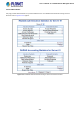
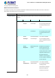
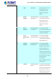
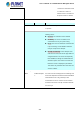
Table Of Contents
- 1. INTRODUCTION
- 2. INSTALLATION
- 3. SWITCH MANAGEMENT
- 4. WEB CONFIGURATION
- 4.1 Main Web Page
- 4.2 System
- 4.2.1 Management
- 4.2.1.1 System Information
- 4.2.1.2 IP Configuration
- 4.2.1.3 IP Status
- 4.2.1.4 ARP Configuration
- 4.2.1.5 Users Configuration
- 4.2.1.6 Privilege Levels
- 4.2.1.7 NTP Configuration
- 4.2.1.7.1 System Time Correction Manually
- 4.2.1.8 Time Configuration
- 4.2.1.9 UPnP
- 4.2.1.10 DHCP Relay
- 4.2.1.11 DHCP Relay Statistics
- 4.2.1.12 CPU Load
- 4.2.1.13 System Log
- 4.2.1.14 Detailed Log
- 4.2.1.15 Remote Syslog
- 4.2.1.16 SMTP Configuration
- 4.2.2 Simple Network Management Protocol
- 4.2.3 RMON
- 4.2.4 DHCP server
- 4.2.5 Remote Management
- 4.2.1 Management
- 4.3 Switching
- 4.3.1 Port Management
- 4.3.2 Link Aggregation
- 4.3.3 VLAN
- 4.3.3.1 VLAN Overview
- 4.3.3.2 IEEE 802.1Q VLAN
- 4.3.3.3 VLAN Port Configuration
- 4.3.3.4 VLAN Membership Status
- 4.3.3.5 VLAN Port Status
- 4.3.3.6 Private VLAN
- 4.3.3.7 Port Isolation
- 4.3.3.8 VLAN setting example:
- 4.3.3.8.1 Two Separate 802.1Q VLANs
- 4.3.3.8.2 VLAN Trunking between two 802.1Q aware switches
- 4.3.3.8.3 Port Isolate
- 4.3.3.9 MAC-based VLAN
- 4.3.3.10 IP Subnet-based VLAN
- 4.3.3.11 Protocol-based VLAN
- 4.3.3.12 Protocol-based VLAN Membership
- 4.3.4 VLAN Translation
- 4.3.5 Spanning Tree Protocol
- 4.3.6 Multicast
- 4.3.7 MLD Snooping
- 4.3.8 MVR (Multicast VLAN Registration)
- 4.3.9 LLDP
- 4.3.10 MAC Address Table
- 4.3.11 Loop Protection
- 4.3.12 UDLD
- 4.3.13 GVRP
- 4.4 Quality of Service
- 4.5 Security
- 4.6 Power over Ethernet
- 4.7 ONVIF
- 4.8 Maintenance
- 4.8.1 Web Firmware Upgrade
- 4.8.2 Save Startup Config
- 4.8.3 Configuration Download
- 4.8.4 Configuration Upload
- 4.8.5 Configure Activate
- 4.8.6 Configure Delete
- 4.8.7 Image Select
- 4.8.8 Factory Default
- 4.8.9 System Reboot
- 4.8.10 Ping
- 4.8.11 IPv6 Ping
- 4.8.12 Remote IP Ping
- 4.8.13 Cable Diagnostics
- 4.8.14 Traceroute (IPv4)
- 4.8.15 Traceroute (IPv6)
- 5. COMMAND LINE MODE
- 6. SWITCH OPERATION
- 7. TROUBLESHOOTING
- APPENDIX A: Networking Connection
- APPENDIX B : GLOSSARY

User’s Manual of GS-5220-8P2T2S Managed Switch
264
4.5.2.4 RADIUS Overview
This page provides an overview of the status of the RADIUS servers configurable on the authentication configuration page. The
RADIUS Authentication/Accounting Server Overview screen in Figure 4-5-2-4 appears.
Figure 4-5-2-4: RADIUS Authentication/Accounting Server Overview Page Screenshot
The page includes the following fields:
RADIUS Authentication Server Status Overview
Object Description
• #
The RADIUS server number. Click to navigate to detailed statistics for this server.
• IP Address
The IP address and UDP port number (in <IP Address>:<UDP Port> notation) of this server.
• Authentication
Port
UDP port number for authentication.
• Authentication
Status
The current status of the server. This field takes one of the following values:
Disabled: The server is disabled.
Not Ready: The server is enabled, but IP communication is not yet up and running.
Ready: The server is enabled, IP communication is up and running, and the RADIUS module
is ready to accept access attempts.
Dead (X seconds left): Access attempts were made to this server, but it did not reply within
the configured timeout. The server has temporarily been disabled, but will get re-enabled
when the dead-time expires. The number of seconds left before this occurs is displayed in
parentheses. This state is only reachable when more than one server is enabled.
• Accounting
Port
UDP port number for accounting
• Accounting
Status
The current status of the server. This field takes one of the following values:
Disabled: The server is disabled.
Not Ready: The server is enabled, but IP communication is not yet up and running.
Ready: The server is enabled, IP communication is up and running, and the RADIUS module
is ready to accept access attempts.
Dead (X seconds left): Access attempts were made to this server, but it did not reply within