
User's Manual
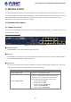
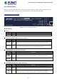
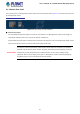
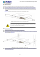
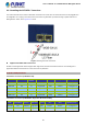
Table Of Contents
- 1. INTRODUCTION
- 2. INSTALLATION
- 3. SWITCH MANAGEMENT
- 4. WEB CONFIGURATION
- 4.1 Main Web Page
- 4.2 System
- 4.2.1 Management
- 4.2.1.1 System Information
- 4.2.1.2 IP Configuration
- 4.2.1.3 IP Status
- 4.2.1.4 ARP Configuration
- 4.2.1.5 Users Configuration
- 4.2.1.6 Privilege Levels
- 4.2.1.7 NTP Configuration
- 4.2.1.7.1 System Time Correction Manually
- 4.2.1.8 Time Configuration
- 4.2.1.9 UPnP
- 4.2.1.10 DHCP Relay
- 4.2.1.11 DHCP Relay Statistics
- 4.2.1.12 CPU Load
- 4.2.1.13 System Log
- 4.2.1.14 Detailed Log
- 4.2.1.15 Remote Syslog
- 4.2.1.16 SMTP Configuration
- 4.2.2 Simple Network Management Protocol
- 4.2.3 RMON
- 4.2.4 DHCP server
- 4.2.5 Remote Management
- 4.2.1 Management
- 4.3 Switching
- 4.3.1 Port Management
- 4.3.2 Link Aggregation
- 4.3.3 VLAN
- 4.3.3.1 VLAN Overview
- 4.3.3.2 IEEE 802.1Q VLAN
- 4.3.3.3 VLAN Port Configuration
- 4.3.3.4 VLAN Membership Status
- 4.3.3.5 VLAN Port Status
- 4.3.3.6 Private VLAN
- 4.3.3.7 Port Isolation
- 4.3.3.8 VLAN setting example:
- 4.3.3.8.1 Two Separate 802.1Q VLANs
- 4.3.3.8.2 VLAN Trunking between two 802.1Q aware switches
- 4.3.3.8.3 Port Isolate
- 4.3.3.9 MAC-based VLAN
- 4.3.3.10 IP Subnet-based VLAN
- 4.3.3.11 Protocol-based VLAN
- 4.3.3.12 Protocol-based VLAN Membership
- 4.3.4 VLAN Translation
- 4.3.5 Spanning Tree Protocol
- 4.3.6 Multicast
- 4.3.7 MLD Snooping
- 4.3.8 MVR (Multicast VLAN Registration)
- 4.3.9 LLDP
- 4.3.10 MAC Address Table
- 4.3.11 Loop Protection
- 4.3.12 UDLD
- 4.3.13 GVRP
- 4.4 Quality of Service
- 4.5 Security
- 4.6 Power over Ethernet
- 4.7 ONVIF
- 4.8 Maintenance
- 4.8.1 Web Firmware Upgrade
- 4.8.2 Save Startup Config
- 4.8.3 Configuration Download
- 4.8.4 Configuration Upload
- 4.8.5 Configure Activate
- 4.8.6 Configure Delete
- 4.8.7 Image Select
- 4.8.8 Factory Default
- 4.8.9 System Reboot
- 4.8.10 Ping
- 4.8.11 IPv6 Ping
- 4.8.12 Remote IP Ping
- 4.8.13 Cable Diagnostics
- 4.8.14 Traceroute (IPv4)
- 4.8.15 Traceroute (IPv6)
- 5. COMMAND LINE MODE
- 6. SWITCH OPERATION
- 7. TROUBLESHOOTING
- APPENDIX A: Networking Connection
- APPENDIX B : GLOSSARY

User’s Manual of GS-5220-8P2T2S Managed Switch
26
2.1.2 LED Indications
The front panel LEDs indicate instant status of power status,port links/PoE-in-use and data activity; they help monitor and
troubleshoot when needed. Figures 2-1-2 show the LED indications of the L2+ Managed PoE+ Switch.
GS-5220-8P2T2S LED indication
Figure 2-1-2: LED Panel of GS-5220-8P2T2S
LED Definition
■ System
LED Color Function
PWR Green Lights to indicate the Switch has power.
■ Per 10/100/1000BASE-T PoE+ Port (Port 1 to Port 8)
LED Color Function
LNK/ACT Green
Lights: To indicate the link through that port is successfully established.
Blink: To indicate that the switch is actively sending or receiving data over that port.
PoE In-Use Amber
Lights: To indicate the port is providing DC in-line power.
Off: To indicate the connected device is not a PoE Powered Device (PD).
■ 10/100/1000BASE-T interfaces (Port-9 to Port-10)
LED
Color Function
1000
LNK/ACT
Green
Lights:
To indicate the link through that port is successfully established at 1000Mbps.
Blink:
To indicate that the switch is actively sending or receiving data over that port.
10/100
LNK/ACT
Amber
Lights:
To indicate the link through that port is successfully established at 10Mbps or 100Mbps.
Blink: To indicate that the switch is actively sending or receiving data over that port.
■ 100/1000BASE-X SFP Interfaces (Port-11 to Port-12)
LED
Color Function
1000
LNK/ACT
Green
Lights: To indicate the link through that port is successfully established at 1000Mbps.
Blink: To indicate that the switch is actively sending or receiving data over that port.
100
LNK/ACT
Amber
Lights: To indicate the link through that port is successfully established at 100Mbps.
Blink: To indicate that the switch is actively sending or receiving data over that port.