
User's Manual
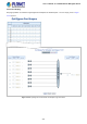
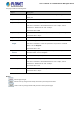
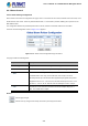

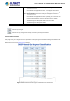
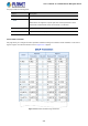

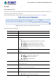
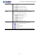
Table Of Contents
- 1. INTRODUCTION
- 2. INSTALLATION
- 3. SWITCH MANAGEMENT
- 4. WEB CONFIGURATION
- 4.1 Main Web Page
- 4.2 System
- 4.2.1 Management
- 4.2.1.1 System Information
- 4.2.1.2 IP Configuration
- 4.2.1.3 IP Status
- 4.2.1.4 ARP Configuration
- 4.2.1.5 Users Configuration
- 4.2.1.6 Privilege Levels
- 4.2.1.7 NTP Configuration
- 4.2.1.7.1 System Time Correction Manually
- 4.2.1.8 Time Configuration
- 4.2.1.9 UPnP
- 4.2.1.10 DHCP Relay
- 4.2.1.11 DHCP Relay Statistics
- 4.2.1.12 CPU Load
- 4.2.1.13 System Log
- 4.2.1.14 Detailed Log
- 4.2.1.15 Remote Syslog
- 4.2.1.16 SMTP Configuration
- 4.2.2 Simple Network Management Protocol
- 4.2.3 RMON
- 4.2.4 DHCP server
- 4.2.5 Remote Management
- 4.2.1 Management
- 4.3 Switching
- 4.3.1 Port Management
- 4.3.2 Link Aggregation
- 4.3.3 VLAN
- 4.3.3.1 VLAN Overview
- 4.3.3.2 IEEE 802.1Q VLAN
- 4.3.3.3 VLAN Port Configuration
- 4.3.3.4 VLAN Membership Status
- 4.3.3.5 VLAN Port Status
- 4.3.3.6 Private VLAN
- 4.3.3.7 Port Isolation
- 4.3.3.8 VLAN setting example:
- 4.3.3.8.1 Two Separate 802.1Q VLANs
- 4.3.3.8.2 VLAN Trunking between two 802.1Q aware switches
- 4.3.3.8.3 Port Isolate
- 4.3.3.9 MAC-based VLAN
- 4.3.3.10 IP Subnet-based VLAN
- 4.3.3.11 Protocol-based VLAN
- 4.3.3.12 Protocol-based VLAN Membership
- 4.3.4 VLAN Translation
- 4.3.5 Spanning Tree Protocol
- 4.3.6 Multicast
- 4.3.7 MLD Snooping
- 4.3.8 MVR (Multicast VLAN Registration)
- 4.3.9 LLDP
- 4.3.10 MAC Address Table
- 4.3.11 Loop Protection
- 4.3.12 UDLD
- 4.3.13 GVRP
- 4.4 Quality of Service
- 4.5 Security
- 4.6 Power over Ethernet
- 4.7 ONVIF
- 4.8 Maintenance
- 4.8.1 Web Firmware Upgrade
- 4.8.2 Save Startup Config
- 4.8.3 Configuration Download
- 4.8.4 Configuration Upload
- 4.8.5 Configure Activate
- 4.8.6 Configure Delete
- 4.8.7 Image Select
- 4.8.8 Factory Default
- 4.8.9 System Reboot
- 4.8.10 Ping
- 4.8.11 IPv6 Ping
- 4.8.12 Remote IP Ping
- 4.8.13 Cable Diagnostics
- 4.8.14 Traceroute (IPv4)
- 4.8.15 Traceroute (IPv6)
- 5. COMMAND LINE MODE
- 6. SWITCH OPERATION
- 7. TROUBLESHOOTING
- APPENDIX A: Networking Connection
- APPENDIX B : GLOSSARY

User’s Manual of GS-5220-8P2T2S Managed Switch
239
4.4.5 QCL
4.4.5.1 QoS Control List
This page shows the QoS Control List(QCL), which is made up of the QCEs. Each row describes a QCE that is defined. The
maximum number of QCEs is 256 on each switch.
Click on the lowest plus sign to add a new QCE to the list. The QoS Control List screen in Figure 4-4-5-1 appears.
Figure 4-4-5-1: QoS Control List Configuration Page Screenshot
The page includes the following fields:
Object Description
• QCE#
Indicates the index of QCE.
• Port
Indicates the list of ports configured with the QCE.
• DMAC
Specify the type of Destination MAC addresses for incoming frame. Possible
values are:
■ Any: All types of Destination MAC addresses are allowed.
■ Unicast: Only Unicast MAC addresses are allowed.
■ Multicast: Only Multicast MAC addresses are allowed.
■ Broadcast: Only Broadcast MAC addresses are allowed.
The default value is 'Any'.
• SMAC
Displays the OUI field of Source MAC address, i.e. first three octet (byte) of MAC
address.
• Tag Type
Indicates tag type. Possible values are:
■ Any: Match tagged and untagged frames.
■ Untagged: Match untagged frames.
■ Tagged: Match tagged frames.
The default value is 'Any'
• VID
Indicates (VLAN ID), either a specific VID or range of VIDs. VID can be in the
range 1-4095 or 'Any'
• PCP
Priority Code Point: Valid value PCP are specific(0, 1, 2, 3, 4, 5, 6, 7) or
range(0-1, 2-3, 4-5, 6-7, 0-3, 4-7) or 'Any'.
• DEI
Drop Eligible Indicator: Valid value of DEI can be any of values between 0, 1 or
'Any'.
• Frame Type
Indicates the type of frame to look for incoming frames. Possible frame types are:
■ Any: The QCE will match all frame type.