
User's Manual
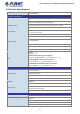
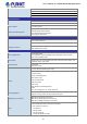
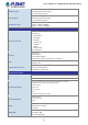

Table Of Contents
- 1. INTRODUCTION
- 2. INSTALLATION
- 3. SWITCH MANAGEMENT
- 4. WEB CONFIGURATION
- 4.1 Main Web Page
- 4.2 System
- 4.2.1 Management
- 4.2.1.1 System Information
- 4.2.1.2 IP Configuration
- 4.2.1.3 IP Status
- 4.2.1.4 ARP Configuration
- 4.2.1.5 Users Configuration
- 4.2.1.6 Privilege Levels
- 4.2.1.7 NTP Configuration
- 4.2.1.7.1 System Time Correction Manually
- 4.2.1.8 Time Configuration
- 4.2.1.9 UPnP
- 4.2.1.10 DHCP Relay
- 4.2.1.11 DHCP Relay Statistics
- 4.2.1.12 CPU Load
- 4.2.1.13 System Log
- 4.2.1.14 Detailed Log
- 4.2.1.15 Remote Syslog
- 4.2.1.16 SMTP Configuration
- 4.2.2 Simple Network Management Protocol
- 4.2.3 RMON
- 4.2.4 DHCP server
- 4.2.5 Remote Management
- 4.2.1 Management
- 4.3 Switching
- 4.3.1 Port Management
- 4.3.2 Link Aggregation
- 4.3.3 VLAN
- 4.3.3.1 VLAN Overview
- 4.3.3.2 IEEE 802.1Q VLAN
- 4.3.3.3 VLAN Port Configuration
- 4.3.3.4 VLAN Membership Status
- 4.3.3.5 VLAN Port Status
- 4.3.3.6 Private VLAN
- 4.3.3.7 Port Isolation
- 4.3.3.8 VLAN setting example:
- 4.3.3.8.1 Two Separate 802.1Q VLANs
- 4.3.3.8.2 VLAN Trunking between two 802.1Q aware switches
- 4.3.3.8.3 Port Isolate
- 4.3.3.9 MAC-based VLAN
- 4.3.3.10 IP Subnet-based VLAN
- 4.3.3.11 Protocol-based VLAN
- 4.3.3.12 Protocol-based VLAN Membership
- 4.3.4 VLAN Translation
- 4.3.5 Spanning Tree Protocol
- 4.3.6 Multicast
- 4.3.7 MLD Snooping
- 4.3.8 MVR (Multicast VLAN Registration)
- 4.3.9 LLDP
- 4.3.10 MAC Address Table
- 4.3.11 Loop Protection
- 4.3.12 UDLD
- 4.3.13 GVRP
- 4.4 Quality of Service
- 4.5 Security
- 4.6 Power over Ethernet
- 4.7 ONVIF
- 4.8 Maintenance
- 4.8.1 Web Firmware Upgrade
- 4.8.2 Save Startup Config
- 4.8.3 Configuration Download
- 4.8.4 Configuration Upload
- 4.8.5 Configure Activate
- 4.8.6 Configure Delete
- 4.8.7 Image Select
- 4.8.8 Factory Default
- 4.8.9 System Reboot
- 4.8.10 Ping
- 4.8.11 IPv6 Ping
- 4.8.12 Remote IP Ping
- 4.8.13 Cable Diagnostics
- 4.8.14 Traceroute (IPv4)
- 4.8.15 Traceroute (IPv6)
- 5. COMMAND LINE MODE
- 6. SWITCH OPERATION
- 7. TROUBLESHOOTING
- APPENDIX A: Networking Connection
- APPENDIX B : GLOSSARY

User’s Manual of GS-5220-8P2T2S Managed Switch
21
1.5 Product Specifications
Product GS-5220-8P2T2S
Hardware Specifications
Copper Ports 10 10/ 100/1000BASE-T RJ45 auto-MDI/MDI-X ports
SFP mini-GBIC Interfaces
2 x 100/1000BASE-X SFP interfaces with Port-11 to Port-12
Supports 100/1000Mbps dual mode and DDM
PoE Injector Port 8 ports with 802.3at/af PoE injector function with Port-1 to Port-8
Console 1 x RJ45 serial port (115200, 8, N, 1)
Reset Button
< 5 sec: System reboot
> 5 sec: Factory Default
Smart Fan
1
Power Requirements
100~240V AC, 50/60Hz, 4A
Power Consumption
(Full Loading)
282 watts/962BTU
ESD Protection
6KV DC
Dimensions (W x D x H)
330 x200 x 44 mm, 1U high
Weight 3.9 kg
LED
System:
Power (Green)
PoE Ethernet Interfaces (Port 1 to Port 8):
LNK/ACT (10/100/1000Mbps, Green), PoE In-Use (Amber)
10/100/1000BASE-T Ports (Port 9 to port 10):
1000 (LNK/ACT, Green), 10/100 (LNK/ACT, Amber)
100/1000Mbps SFP Interfaces (Port 11 to Port 12):
1000 (LNK/ACT, Green), 100 (LNK/ACT, Amber)
Switching
Switch Architecture Store-and-Forward
Switch Fabric 24Gbps /non-blocking
Throughput 17.76Mpps@64Bytes
Address Table 8K entries, automatic source address learning and ageing
SDRAM
128Mbytes
Flash
64Mbytes
Flow Control
IEEE 802.3x pause frame for full duplex
Back pressure for half duplex
Jumbo Frame 9K bytes
Power over Ethernet Specifications
PoE Standard
IEEE 802.3at Power over Ethernet Plus PSE
PoE Power Supply Type
End-span
PoE Power Output
Per port 54V DC, 590mA. max. 30.8 watts
Power Pin Assignment
1/2(+), 3/6(-)
PoE Power Budget
240 watts max. @25 degrees C