
User's Manual
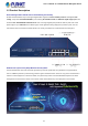
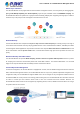
Table Of Contents
- 1. INTRODUCTION
- 2. INSTALLATION
- 3. SWITCH MANAGEMENT
- 4. WEB CONFIGURATION
- 4.1 Main Web Page
- 4.2 System
- 4.2.1 Management
- 4.2.1.1 System Information
- 4.2.1.2 IP Configuration
- 4.2.1.3 IP Status
- 4.2.1.4 ARP Configuration
- 4.2.1.5 Users Configuration
- 4.2.1.6 Privilege Levels
- 4.2.1.7 NTP Configuration
- 4.2.1.7.1 System Time Correction Manually
- 4.2.1.8 Time Configuration
- 4.2.1.9 UPnP
- 4.2.1.10 DHCP Relay
- 4.2.1.11 DHCP Relay Statistics
- 4.2.1.12 CPU Load
- 4.2.1.13 System Log
- 4.2.1.14 Detailed Log
- 4.2.1.15 Remote Syslog
- 4.2.1.16 SMTP Configuration
- 4.2.2 Simple Network Management Protocol
- 4.2.3 RMON
- 4.2.4 DHCP server
- 4.2.5 Remote Management
- 4.2.1 Management
- 4.3 Switching
- 4.3.1 Port Management
- 4.3.2 Link Aggregation
- 4.3.3 VLAN
- 4.3.3.1 VLAN Overview
- 4.3.3.2 IEEE 802.1Q VLAN
- 4.3.3.3 VLAN Port Configuration
- 4.3.3.4 VLAN Membership Status
- 4.3.3.5 VLAN Port Status
- 4.3.3.6 Private VLAN
- 4.3.3.7 Port Isolation
- 4.3.3.8 VLAN setting example:
- 4.3.3.8.1 Two Separate 802.1Q VLANs
- 4.3.3.8.2 VLAN Trunking between two 802.1Q aware switches
- 4.3.3.8.3 Port Isolate
- 4.3.3.9 MAC-based VLAN
- 4.3.3.10 IP Subnet-based VLAN
- 4.3.3.11 Protocol-based VLAN
- 4.3.3.12 Protocol-based VLAN Membership
- 4.3.4 VLAN Translation
- 4.3.5 Spanning Tree Protocol
- 4.3.6 Multicast
- 4.3.7 MLD Snooping
- 4.3.8 MVR (Multicast VLAN Registration)
- 4.3.9 LLDP
- 4.3.10 MAC Address Table
- 4.3.11 Loop Protection
- 4.3.12 UDLD
- 4.3.13 GVRP
- 4.4 Quality of Service
- 4.5 Security
- 4.6 Power over Ethernet
- 4.7 ONVIF
- 4.8 Maintenance
- 4.8.1 Web Firmware Upgrade
- 4.8.2 Save Startup Config
- 4.8.3 Configuration Download
- 4.8.4 Configuration Upload
- 4.8.5 Configure Activate
- 4.8.6 Configure Delete
- 4.8.7 Image Select
- 4.8.8 Factory Default
- 4.8.9 System Reboot
- 4.8.10 Ping
- 4.8.11 IPv6 Ping
- 4.8.12 Remote IP Ping
- 4.8.13 Cable Diagnostics
- 4.8.14 Traceroute (IPv4)
- 4.8.15 Traceroute (IPv6)
- 5. COMMAND LINE MODE
- 6. SWITCH OPERATION
- 7. TROUBLESHOOTING
- APPENDIX A: Networking Connection
- APPENDIX B : GLOSSARY

User’s Manual of GS-5220-8P2T2S Managed Switch
18
1.4 Product Features
Physical Port
10-Port 10/100/1000BASE-T RJ45 copper with 8-Port IEEE 802.3at/af Power over Ethernet Injector function
2 100/1000BASE-X mini-GBIC/SFP slots
RJ45 console interface for basic management and setup
Power over Ethernet
Complies with IEEE 802.3at Power over Ethernet Plus/end-span PSE
Up to 8 IEEE 802.3af/802.3at devices powered
Supports PoE power up to 36 watts for each PoE port
Auto detects powered device (PD)
Circuit protection prevents power interference between ports
Remote power feeding up to 100 meters in standard mode and 250m in extended mode
PoE management features
• PoE admin-mode control
• PoE management mode selection
• Per port PoE function enable/disable
• PoE port power feeding priority
• Per PoE port power limit
• PoE Port Status monitoring
• PD classification detection
• Sequence port PoE
• PoE extension
Intelligent PoE features
• Temperature threshold control
• PoE usage threshold control
• PoE schedule
• PD alive check
• LLDP PoE neighbors
Layer 2 Features
■ Prevents packet loss with back pressure (half-duplex) and IEEE 802.3x pause frame flow control (full-duplex)
■ High performance of Store-and-Forward architecture and runt/CRC filtering eliminates erroneous packets to optimize
the network bandwidth
■ Storm Control support
− Broadcast/Multicast/Unicast
■ Supports VLAN
− IEEE 802.1Q tagged VLAN
− Up to 4K VLANs groups, out of 4095 VLAN IDs
− Supports provider bridging (VLAN Q-in-Q, IEEE 802.1ad)
− Private VLAN Edge (PVE)
− Port Isolation
− MAC-based VLAN
− IP Subnet-based VLAN
− Protocol-based VLAN
− VLAN Translation
− Voice VLAN
− GVRP