
GS-5220-Series (V4) User Manual
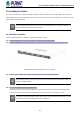
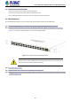
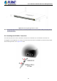
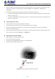

Table Of Contents
- 1. INTRODUCTION
- 2. INSTALLATION
- 3. SWITCH MANAGEMENT
- 4. WEB CONFIGURATION
- 4.1 Main Web Page
- 4.2 System
- 4.2.1 Management
- 4.2.1.1 System Information
- 4.2.1.2 IP Configuration
- 4.2.1.3 IP Status
- 4.2.1.4 Users Configuration
- 4.2.1.5 Privilege Levels
- 4.2.1.6 NTP Configuration
- 4.2.1.6.1 System Time Correction Manually
- 4.2.1.7 Time Configuration
- 4.2.1.8 UPnP
- 4.2.1.9 DHCP Relay
- 4.2.1.10 DHCP Relay Statistics
- 4.2.1.11 CPU Load
- 4.2.1.12 System Log
- 4.2.1.13 Detailed Log
- 4.2.1.14 Remote Syslog
- 4.2.1.15 SMTP Configuration
- 4.2.2 Simple Network Management Protocol
- 4.2.3 RMON
- 4.2.4 DHCP server
- 4.2.1 Management
- 4.3 Switching
- 4.3.1 Port Management
- 4.3.2 Link Aggregation
- 4.3.3 VLAN
- 4.3.3.1 VLAN Overview
- 4.3.3.2 IEEE 802.1Q VLAN
- 4.3.3.3 VLAN Port Configuration
- 4.3.3.4 VLAN Membership Status
- 4.3.3.5 VLAN Port Status
- 4.3.3.6 Private VLAN
- 4.3.3.7 Port Isolation
- 4.3.3.8 VLAN setting example:
- 4.3.3.8.1 Two Separate 802.1Q VLANs
- 4.3.3.8.2 VLAN Trunking between two 802.1Q aware switches
- 4.3.3.8.3 Port Isolate
- 4.3.3.9 MAC-based VLAN
- 4.3.3.10 Protocol-based VLAN
- 4.3.3.11 Protocol-based VLAN Membership
- 4.3.4 Spanning Tree Protocol
- 4.3.5 IGMP Snooping
- 4.3.6 MLD Snooping
- 4.3.7 MVR (Multicast VLAN Registration)
- 4.3.8 LLDP
- 4.3.9 MAC Address Table
- 4.3.10 Loop Protection
- 4.3.11 UDLD
- 4.3.12 GVRP
- 4.3.13 Link OAM
- 4.4 Routing
- 4.5 Quality of Service
- 4.6 Security
- 4.7 Power over Ethernet
- 4.8 Ring
- 4.9 ONVIF
- 4.10 Maintenance
- 5. SWITCH OPERATION
- 6. TROUBLESHOOTING
- APPENDIX A: Networking Connection
- APPENDIX B : GLOSSARY

User’s Manual of GS-5220 PoE Series Managed Switch
59
1. Before we connect the GS-5220 PoE series to the other network device, we have to make sure both sides of the SFP
transceivers are with the same media type, for example: 1000BASE-SX to 1000BASE-SX, 1000BASE-LX to
1000BASE-LX.
2. Check whether the fiber-optic cable type matches with the SFP transceiver requirement.
To connect to 1000BASE-SX SFP transceiver, please use the multi-mode fiber cable with one side being the male
duplex LC connector type.
To connect to 1000BASE-LX SFP transceiver, please use the single-mode fiber cable with one side being the male
duplex LC connector type.
Connecting the Fiber Cable
1. Insert the duplex LC connector into the SFP/SFP+ transceiver.
2. Connect the other end of the cable to a device with SFP/SFP+ transceiver installed.
3. Check the LNK/ACT LED of the SFP/SFP+ slot on the front of the Managed Switch. Ensure that the SFP/SFP+
transceiver is operating correctly.
4. Check the Link mode of the SFP/SFP+ port if the link fails. To function with some fiber-NICs or Media Converters, user
has to set the port Link mode to “10G Force”, or “1000M Force”.
Removing the Transceiver Module
1. Make sure there is no network activity anymore.
2. Remove the Fiber-Optic Cable gently.
3. Lift up the lever of the MGB module and turn it to a horizontal position.
4. Pull out the module gently through the lever.
Figure 2-2-5: How to Pull Out the SFP/SFP+ Transceiver