
GS-5220-Series (V4) User Manual
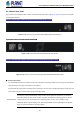
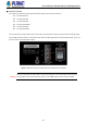
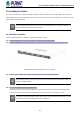
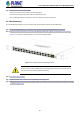
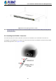
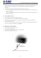

Table Of Contents
- 1. INTRODUCTION
- 2. INSTALLATION
- 3. SWITCH MANAGEMENT
- 4. WEB CONFIGURATION
- 4.1 Main Web Page
- 4.2 System
- 4.2.1 Management
- 4.2.1.1 System Information
- 4.2.1.2 IP Configuration
- 4.2.1.3 IP Status
- 4.2.1.4 Users Configuration
- 4.2.1.5 Privilege Levels
- 4.2.1.6 NTP Configuration
- 4.2.1.6.1 System Time Correction Manually
- 4.2.1.7 Time Configuration
- 4.2.1.8 UPnP
- 4.2.1.9 DHCP Relay
- 4.2.1.10 DHCP Relay Statistics
- 4.2.1.11 CPU Load
- 4.2.1.12 System Log
- 4.2.1.13 Detailed Log
- 4.2.1.14 Remote Syslog
- 4.2.1.15 SMTP Configuration
- 4.2.2 Simple Network Management Protocol
- 4.2.3 RMON
- 4.2.4 DHCP server
- 4.2.1 Management
- 4.3 Switching
- 4.3.1 Port Management
- 4.3.2 Link Aggregation
- 4.3.3 VLAN
- 4.3.3.1 VLAN Overview
- 4.3.3.2 IEEE 802.1Q VLAN
- 4.3.3.3 VLAN Port Configuration
- 4.3.3.4 VLAN Membership Status
- 4.3.3.5 VLAN Port Status
- 4.3.3.6 Private VLAN
- 4.3.3.7 Port Isolation
- 4.3.3.8 VLAN setting example:
- 4.3.3.8.1 Two Separate 802.1Q VLANs
- 4.3.3.8.2 VLAN Trunking between two 802.1Q aware switches
- 4.3.3.8.3 Port Isolate
- 4.3.3.9 MAC-based VLAN
- 4.3.3.10 Protocol-based VLAN
- 4.3.3.11 Protocol-based VLAN Membership
- 4.3.4 Spanning Tree Protocol
- 4.3.5 IGMP Snooping
- 4.3.6 MLD Snooping
- 4.3.7 MVR (Multicast VLAN Registration)
- 4.3.8 LLDP
- 4.3.9 MAC Address Table
- 4.3.10 Loop Protection
- 4.3.11 UDLD
- 4.3.12 GVRP
- 4.3.13 Link OAM
- 4.4 Routing
- 4.5 Quality of Service
- 4.6 Security
- 4.7 Power over Ethernet
- 4.8 Ring
- 4.9 ONVIF
- 4.10 Maintenance
- 5. SWITCH OPERATION
- 6. TROUBLESHOOTING
- APPENDIX A: Networking Connection
- APPENDIX B : GLOSSARY

User’s Manual of GS-5220 PoE Series Managed Switch
52
2.1.3 Switch Rear Panel
The rear panel of the Managed Switch consists of the AC/DC inlet power socket. Figures 2-1-31 to 2-1-33 show the rear panels
of the Managed Switches.
GS-5220-24P4X/24PL4X/48P4X/16UP4S2X/24UP4X/24UPL4X Rear Panel
Figure 2-1-31: Rear Panel of GS-5220-24P(L)4X/48P4X/16UP4S2X/24UP(L)4X
GS-5220-8UP2T2X/GS-5220-8P2T2X Rear Panel
Figure 2-1-32: Rear Panel of GS-5220-8UP2T2X/GS-5220-8P2T2X
GS-5220-24P4XR/24PL4XR/48PL4XR/16UP4S2XR/24UP4XR/24UPL4XR Rear Panel
Figure 2-1-33: Rear Panel of GS-5220-24P(L)4XR/48PL4XR/16UP4S2XR/24UP(L)4XR
■ AC Power Receptacle
For compatibility with electrical voltages in most areas of the world, the Managed Switch’s power supply can automatically
adjust line power in the range of 100-240V AC and 50/60 Hz.
Plug the female end of the power cord firmly into the receptacle on the rear panel of the Managed Switch and the other end
of the power cord into an electrical outlet and the power will be ready.
Power Notice:
The device is a power-required device, which means it will not work till it is powered. If your networks
should be active all the time, please consider using UPS (Uninterrupted Power Supply) for your device.
It will prevent you from network data loss or network downtime. In some areas, installing a surge
suppression device may also help to protect your Managed
Switch from being damaged by unregulated
surge or current to the Switch or the power adapter.