
GS-5220-Series (V4) User Manual
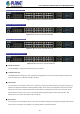
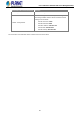
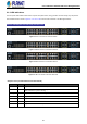
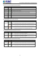
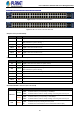
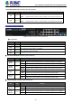
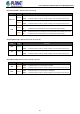
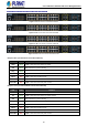
Table Of Contents
- 1. INTRODUCTION
- 2. INSTALLATION
- 3. SWITCH MANAGEMENT
- 4. WEB CONFIGURATION
- 4.1 Main Web Page
- 4.2 System
- 4.2.1 Management
- 4.2.1.1 System Information
- 4.2.1.2 IP Configuration
- 4.2.1.3 IP Status
- 4.2.1.4 Users Configuration
- 4.2.1.5 Privilege Levels
- 4.2.1.6 NTP Configuration
- 4.2.1.6.1 System Time Correction Manually
- 4.2.1.7 Time Configuration
- 4.2.1.8 UPnP
- 4.2.1.9 DHCP Relay
- 4.2.1.10 DHCP Relay Statistics
- 4.2.1.11 CPU Load
- 4.2.1.12 System Log
- 4.2.1.13 Detailed Log
- 4.2.1.14 Remote Syslog
- 4.2.1.15 SMTP Configuration
- 4.2.2 Simple Network Management Protocol
- 4.2.3 RMON
- 4.2.4 DHCP server
- 4.2.1 Management
- 4.3 Switching
- 4.3.1 Port Management
- 4.3.2 Link Aggregation
- 4.3.3 VLAN
- 4.3.3.1 VLAN Overview
- 4.3.3.2 IEEE 802.1Q VLAN
- 4.3.3.3 VLAN Port Configuration
- 4.3.3.4 VLAN Membership Status
- 4.3.3.5 VLAN Port Status
- 4.3.3.6 Private VLAN
- 4.3.3.7 Port Isolation
- 4.3.3.8 VLAN setting example:
- 4.3.3.8.1 Two Separate 802.1Q VLANs
- 4.3.3.8.2 VLAN Trunking between two 802.1Q aware switches
- 4.3.3.8.3 Port Isolate
- 4.3.3.9 MAC-based VLAN
- 4.3.3.10 Protocol-based VLAN
- 4.3.3.11 Protocol-based VLAN Membership
- 4.3.4 Spanning Tree Protocol
- 4.3.5 IGMP Snooping
- 4.3.6 MLD Snooping
- 4.3.7 MVR (Multicast VLAN Registration)
- 4.3.8 LLDP
- 4.3.9 MAC Address Table
- 4.3.10 Loop Protection
- 4.3.11 UDLD
- 4.3.12 GVRP
- 4.3.13 Link OAM
- 4.4 Routing
- 4.5 Quality of Service
- 4.6 Security
- 4.7 Power over Ethernet
- 4.8 Ring
- 4.9 ONVIF
- 4.10 Maintenance
- 5. SWITCH OPERATION
- 6. TROUBLESHOOTING
- APPENDIX A: Networking Connection
- APPENDIX B : GLOSSARY

User’s Manual of GS-5220 PoE Series Managed Switch
45
GS-5220-48P4X(R)/GS-5220-48PL4X(R) LED Indication
Figure 2-1-21: Front Panel of GS-5220-48P4X
Figure 2-1-22: Front Panel of GS-5220-48PL4XR
System / Alert (GS-5220-48P4X)
LED Color Function
PWR Green
Lights to indicate that the Switch has power.
SYS Green
Lights to indicate the system is working.
Off to indicate the system is booting.
Ring Green
Lights to indicate that the ERPS Ring has been created successfully.
FAN 1 Red
Lights to indicate that FAN1 is down.
FAN 2 Red
Lights to indicate that FAN2 is down.
FAN 3 Red
Lights to indicate that FAN3 is down.
PoE PWR Red
Lights to indicate that the PoE power is down.
System / Alert (GS-5220-48PL4XR)
LED Color Function
AC Green
Lights to indicate that the Switch has power from AC
DC Green
Lights to indicate that the Switch has power from DC
SYS Green
Lights to indicate the system is working.
Off to indicate the system is booting.
Ring Green
Lights to indicate that the ERPS Ring has been created successfully.
FAN 1 Red
Lights to indicate that FAN1 is down.
FAN 2 Red
Lights to indicate that FAN2 is down.
FAN 3 Red
Lights to indicate that FAN3 is down.
PoE PWR Red
Lights to indicate that the PoE power is down.
10/100/1000BASE-T Interfaces (Port-1 to Port-48)
LED Color Function
Ethernet
Green
Lights: To indicate that the port is operating at 1000Mbps.
Blinks: To indicate that the switch is actively sending or receiving data over that port.
Amber
Lights: To indicate that the port is operating at 10/100Mbps.
Blinks: To indicate that the switch is actively sending or receiving data over that port.
PoE Amber
Lights: To indicate the port is providing DC in-line power
Off: To indicate the connected device is not a PoE Powered Device (PD)