
GS-5220-Series (V4) User Manual
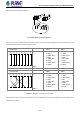

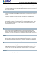
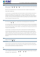
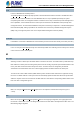
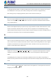
Table Of Contents
- 1. INTRODUCTION
- 2. INSTALLATION
- 3. SWITCH MANAGEMENT
- 4. WEB CONFIGURATION
- 4.1 Main Web Page
- 4.2 System
- 4.2.1 Management
- 4.2.1.1 System Information
- 4.2.1.2 IP Configuration
- 4.2.1.3 IP Status
- 4.2.1.4 Users Configuration
- 4.2.1.5 Privilege Levels
- 4.2.1.6 NTP Configuration
- 4.2.1.6.1 System Time Correction Manually
- 4.2.1.7 Time Configuration
- 4.2.1.8 UPnP
- 4.2.1.9 DHCP Relay
- 4.2.1.10 DHCP Relay Statistics
- 4.2.1.11 CPU Load
- 4.2.1.12 System Log
- 4.2.1.13 Detailed Log
- 4.2.1.14 Remote Syslog
- 4.2.1.15 SMTP Configuration
- 4.2.2 Simple Network Management Protocol
- 4.2.3 RMON
- 4.2.4 DHCP server
- 4.2.1 Management
- 4.3 Switching
- 4.3.1 Port Management
- 4.3.2 Link Aggregation
- 4.3.3 VLAN
- 4.3.3.1 VLAN Overview
- 4.3.3.2 IEEE 802.1Q VLAN
- 4.3.3.3 VLAN Port Configuration
- 4.3.3.4 VLAN Membership Status
- 4.3.3.5 VLAN Port Status
- 4.3.3.6 Private VLAN
- 4.3.3.7 Port Isolation
- 4.3.3.8 VLAN setting example:
- 4.3.3.8.1 Two Separate 802.1Q VLANs
- 4.3.3.8.2 VLAN Trunking between two 802.1Q aware switches
- 4.3.3.8.3 Port Isolate
- 4.3.3.9 MAC-based VLAN
- 4.3.3.10 Protocol-based VLAN
- 4.3.3.11 Protocol-based VLAN Membership
- 4.3.4 Spanning Tree Protocol
- 4.3.5 IGMP Snooping
- 4.3.6 MLD Snooping
- 4.3.7 MVR (Multicast VLAN Registration)
- 4.3.8 LLDP
- 4.3.9 MAC Address Table
- 4.3.10 Loop Protection
- 4.3.11 UDLD
- 4.3.12 GVRP
- 4.3.13 Link OAM
- 4.4 Routing
- 4.5 Quality of Service
- 4.6 Security
- 4.7 Power over Ethernet
- 4.8 Ring
- 4.9 ONVIF
- 4.10 Maintenance
- 5. SWITCH OPERATION
- 6. TROUBLESHOOTING
- APPENDIX A: Networking Connection
- APPENDIX B : GLOSSARY

User’s Manual of GS-5220 PoE Series Managed Switch
431
The standard cable, RJ45 pin assignment
2 1 3 6
1
2
3
6
2 1
3 6
The standard RJ45 receptacle/connector
There are 8 wires on a standard UTP/STP cable and each wire is color-coded. The following shows the pin allocation and color
of straight-through cable and crossover cable connection:
Straight Cable SIDE 1 SIDE 2
SIDE 1
1 = White / Amber
2 = Amber
3 = White / Green
4 = Blue
5 = White / Blue
6 = Green
7 = White / Brown
8 = Brown
1 = White / Amber
2 = Amber
3 = White / Green
4 = Blue
5 = White / Blue
6 = Green
7 = White / Brown
8 = Brown
SIDE 2
Crossover Cable SIDE 1 SIDE 2
SIDE 1
1 = White / Amber
2 = Amber
3 = White / Green
4 = Blue
5 = White / Blue
6 = Green
7 = White / Brown
8 = Brown
1 = White / Green
2 = Green
3 = White / Amber
4 = Blue
5 = White / Blue
6 = Amber
7 = White / Brown
8 = Brown
SIDE 2
Figure A-1: Straight-through and Crossover Cable
Please make sure your connected cables are with the same pin assignment and color as the above picture before deploying the
cables into your network.
1 2 3 4 5 6 7 8
1 2 3 4 5 6 7 8
1 2 3 4 5 6 7 8
1 2 3 4 5 6 7 8