
GS-5220-Series (V4) User Manual
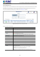
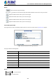
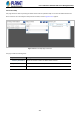
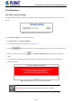
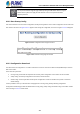
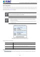
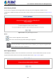
Table Of Contents
- 1. INTRODUCTION
- 2. INSTALLATION
- 3. SWITCH MANAGEMENT
- 4. WEB CONFIGURATION
- 4.1 Main Web Page
- 4.2 System
- 4.2.1 Management
- 4.2.1.1 System Information
- 4.2.1.2 IP Configuration
- 4.2.1.3 IP Status
- 4.2.1.4 Users Configuration
- 4.2.1.5 Privilege Levels
- 4.2.1.6 NTP Configuration
- 4.2.1.6.1 System Time Correction Manually
- 4.2.1.7 Time Configuration
- 4.2.1.8 UPnP
- 4.2.1.9 DHCP Relay
- 4.2.1.10 DHCP Relay Statistics
- 4.2.1.11 CPU Load
- 4.2.1.12 System Log
- 4.2.1.13 Detailed Log
- 4.2.1.14 Remote Syslog
- 4.2.1.15 SMTP Configuration
- 4.2.2 Simple Network Management Protocol
- 4.2.3 RMON
- 4.2.4 DHCP server
- 4.2.1 Management
- 4.3 Switching
- 4.3.1 Port Management
- 4.3.2 Link Aggregation
- 4.3.3 VLAN
- 4.3.3.1 VLAN Overview
- 4.3.3.2 IEEE 802.1Q VLAN
- 4.3.3.3 VLAN Port Configuration
- 4.3.3.4 VLAN Membership Status
- 4.3.3.5 VLAN Port Status
- 4.3.3.6 Private VLAN
- 4.3.3.7 Port Isolation
- 4.3.3.8 VLAN setting example:
- 4.3.3.8.1 Two Separate 802.1Q VLANs
- 4.3.3.8.2 VLAN Trunking between two 802.1Q aware switches
- 4.3.3.8.3 Port Isolate
- 4.3.3.9 MAC-based VLAN
- 4.3.3.10 Protocol-based VLAN
- 4.3.3.11 Protocol-based VLAN Membership
- 4.3.4 Spanning Tree Protocol
- 4.3.5 IGMP Snooping
- 4.3.6 MLD Snooping
- 4.3.7 MVR (Multicast VLAN Registration)
- 4.3.8 LLDP
- 4.3.9 MAC Address Table
- 4.3.10 Loop Protection
- 4.3.11 UDLD
- 4.3.12 GVRP
- 4.3.13 Link OAM
- 4.4 Routing
- 4.5 Quality of Service
- 4.6 Security
- 4.7 Power over Ethernet
- 4.8 Ring
- 4.9 ONVIF
- 4.10 Maintenance
- 5. SWITCH OPERATION
- 6. TROUBLESHOOTING
- APPENDIX A: Networking Connection
- APPENDIX B : GLOSSARY

User’s Manual of GS-5220 PoE Series Managed Switch
417
Figure 4-10-3-1: Configuration Download Page Screenshot
4.10.4 Configuration Upload
Configuration Upload page allows the upload the running-config and startup-config on the switch. Please refer to the Figure
4-10-4-1 shown below.
Figure 4-10-4-1: Configuration Upload Page Screenshot
If the destination is running-config, the file will be applied to the switch configuration. This can be done in two ways:
• Replace mode: The current configuration is fully replaced with the configuration in the uploaded file.
• Merge mode: The uploaded file is merged into running-config.
If the file system is full (i.e. contains the three system files mentioned above plus two other files), it is not possible to create new
files, but an existing file must be overwritten or another deleted first.